With the ongoing increase in module operating current, a reliable junction box is critical for modules which are to last for 25 to 30 years. This article will analyse which factors need to be considered when selecting a junction box for large format modules with different operating currents.
- Standard of rating current for junction box
According to IEC 61215 bypass diode test specifications, the rating current of a junction box should be higher than 1.25 * Isc for a monofacial module. For a bifacial module, bifacial gain should also be considered as per the following equation (IEC61215\IEC61730:2021):
I(rating current) = Isc * (1+30% * ϕ) * 1.25
Where ‘Isc’ is the short circuit current of the module and ϕ its bifaciality.
Bifaciality is normally around 70%±5% and, to allow for a reasonable safety margin for the junction box, its rating current for different modules is shown in the following table:
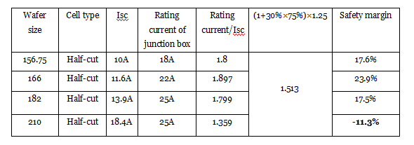
It can be seen that, for modules based on 156.75mm, 166mm and 182mm wafers, there is a sufficient safety margin for the junction box. However, for a bifacial module based on a 210mm wafer, there is no safety margin remaining, which indicates that in some cases the operating current of the module will be higher than the rating current, resulting in possible junction box failure.
2. Analysis of the diode design of a junction box
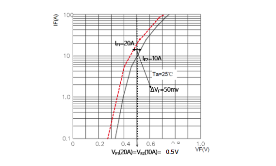
In the case of modules based on 182mm, a 25A junction box with single diode design is reliable due to a sufficient safety margin (17.5%) as stated above. However, if the operating current of a module increases to 18.4A, the safety margin for the 25A junction box becomes insufficient, requiring a significant increase in single diode size. Therefore, for an 18.4A module, a double diode design is applied, resulting in a risk of uneven distribution of current for the double diode and its possible failure. The following figure is a typical forward voltage curve for a 150mil Schottky diode from a PANJIT 30SQ045 datasheet. If the forward voltage drop is VF=50mv, the difference in current passed through the two diodes will be 10A, which will risk their failure.
3. Analysis of the reliability of the junction box
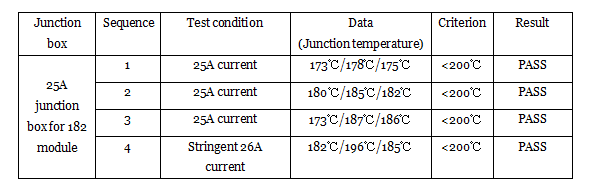
Because junction temperature is critical for junction box reliability, a number of junction temperature tests were conducted as per the following table for LONGi’s Hi-MO 5 bifacial module, based on a 182mm wafer. It can be seen that the 25A junction box for the 182mm module passed all tests, even when the test current was increased to 26A.
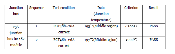
Additionally, in order to simulate comprehensive outdoor ageing factors (high temperature and humidity), a junction temperature test under PCT48h (high pressure ageing test) and 26A current was conducted as set out in the following table. It can be seen that a 25A junction box for a 182mm size module can be considered safe under harsh outdoor conditions.
In summary, in the selection of a reliable junction box for a large current module, safety margin, diode design and performance in harsh conditions are factors which need to be considered. LONGi has adopted the reliable 25A junction box for its Hi-MO 5 module after thorough analysis and testing and will adhere to its long-standing product design concept based on improved LCOE and performance during a product’s full lifecycle.