1 Introduction to Swan bifacial module
1.1 Bifacial market
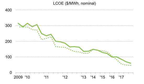
Due to steadily decreasing global subsidy and PPA price for PV project, LCOE of PV stations have been decreasing continuously. High power output of advanced modules can trigger more energy generation and decrease BOS cost, thus promote lower LCOE and the realization of grid parity.
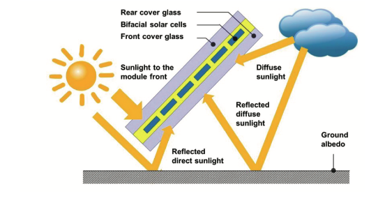
Bifacial module is the module that front and rear sides can generate energy after absorbing the light. Bifacial modules can realize 5%~30% energy gain on different kinds of ground surface, effectively decreasing LCOE of a PV station.
P-type bifacial technology, based on PERC cell technology and integrated with bifacial PECVD, has made breakthrough in recent years [1]. Comparing with N-type bifacial cell technology, PERC bifacial cell is based on low-cost p-type wafer and rear-side aluminum finger metallization, and is compatible with PERC monofacial cell production line without renovation of equipment or purchasing new equipment, thus has lower mass-production cost. Therefore, the p-type bifacial cell has become mainstream for bifacial cells. As for module technology, with the maturely applied glass-glass & glass- transparent backsheet encapsulation method, bifacial modules are mass produced at rapid pace.
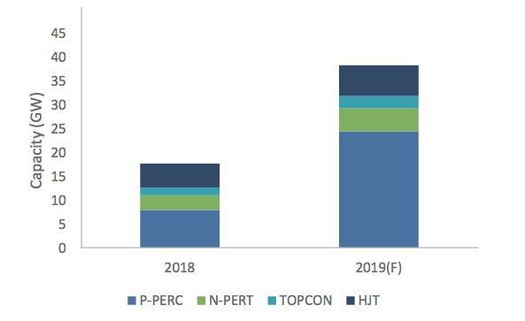
With the maturity and development of bifacial cell and module technology, PERC bifacial products can rapidly realize large-scale production of GW capacity. Energy Trend predicts that bifacial cell capacity will reach 40 GW, among which PERC bifacial cell taking the highest share of 63%.
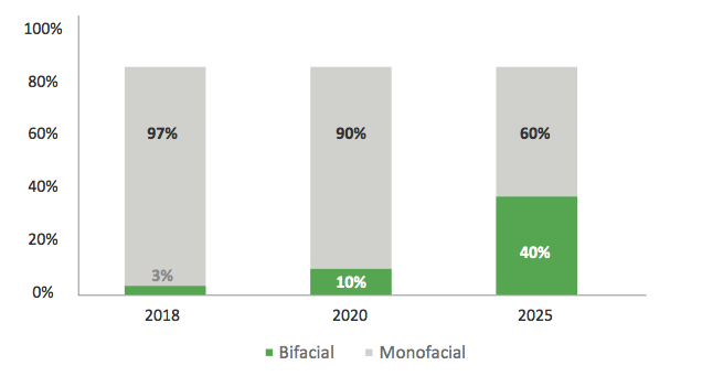
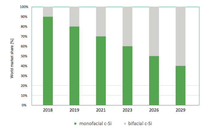
The increase of bifacial module capacity and decrease of price lead to competitive LCOE compared with mono-facial module, thus drive the market of bifacial modules from the demand side. According to Bloomberg NEF [2], bifacial module market share will increase sharply from 10% in 2018 to 40% in 2025. ITRPV also gives an optimistic forecast that bifacial cell will take 60% of market share in 2029.
Top Runner, as the demonstrative project for photovoltaic industry, is famous for its high requirements on the performance of modules and LCOE of PV power stations. In the third batch of Top Runner project, 53% of all modules are bifacial, that strongly proves that the high power, excellent performance and the decisive role in reducing LCOE have helped bifacial modules win the recognition of the Chinese market.
Bifacial modules with high power output, additional energy gain and enhanced power warranty, provide more energy generation to plant owner and become one of the key points to reach grid parity.
1.2 Advantages of Swan bifacial
Jinko has been the world's largest supplier of PV modules for three consecutive years. Jinko, as the most financially viable module brand in the world, takes an increasing market share in various regions, and the quality of modules has also been widely recognized. The company has a strict and conprehensive quality control including IQC, IPQC, FQC, OBA, OQC and SAI, guaranteeing the excellent quality of each shipment. As a result, Jinko has been awarded the best module performance award of PVEL/DNV GL for five consecutive years, and the customer satisfaction has been increasing year by year.
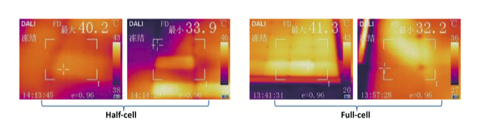
As the star product in 2019, Swan series bifacial module has combined long-term proved quality advantages of Jinko with technological innovations, promoting global grid parity. Jinko Swan bifacial series use 158.75mm size p-type mono-crystalline bifacial cell with high efficiency. Moreover, half-cell technology can decrease internal current thus decrease internal power loss, and as a result the module will have higher power output and good reliability. Compared with 156.75mm full cell module, swan series module can reach power improvement of 15 Wp. As shown in Figure 5, the average temperature difference of half cell is 1.8℃, lower than that of full cell module. The operating temperature is relatively lower than that of the full cell, to reduce hot-spot issue.
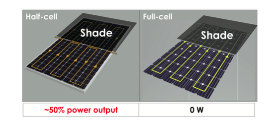
When installed vertically, half-cell technology can effectively cut down the shading loss. In half-cell module, there is parallel connection of the upper part and lower part. When 50% of the module surface is shaded like in the morning or evening, half-cell modules will still generate 50% of its nominal power while the power output of full-cell modules is 0. Moreover half-cell module has better temperature coefficient. The temperature coefficient of Jinko half-cell module is -0.36% W/℃, while that of full-cell module is -0.37% W/℃. Therefore, half-cell module has 2.5% higher power than full-cell module in hot area where the operating temperature of modules could be up to 75℃.
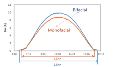
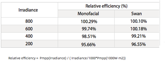
Under low irradiation conditions, such as morning, evening or cloudy days, bifacial module can receive more light and make it easier to achieve the starting voltage of the inverters compared to monofacial module. This makes bifacial module achieve longer power generating time, as shown in Figure 7. Third-party test reports also show that the low irradiance performance of bifacial modules is better compared to monofacial modules.
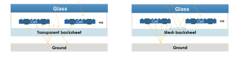
Swan bifacial series can reach 5Wp front side power improvement by utilizing ceramic glass or mesh transparent backsheet. Ceramic glass and mesh backsheet enhance the front-side power via the same way, that is adding one more mesh layer with high reflectivity and UV-resistance, which increases the light reflection of gaps between cells.
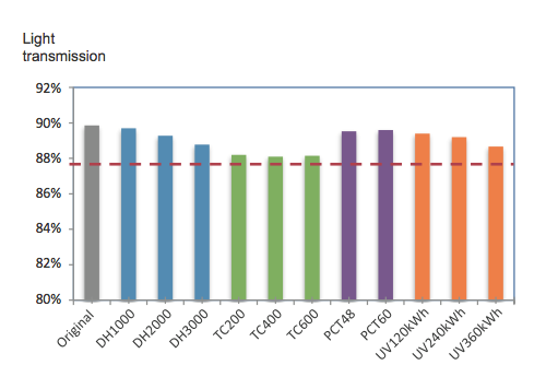
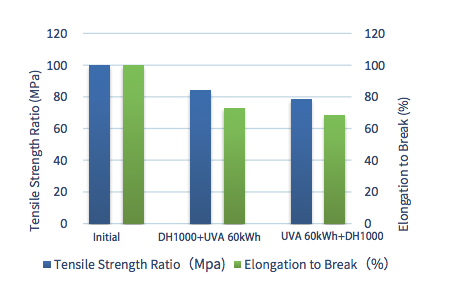
Swan bifacial with dual glass has 30-year performance warranty with first year degradation no more than 2.5% and annual degradation (2nd to 30th year) no more than 0.5%. Two types of frame design (frame & frameless) meet the different demands of customers. Swan bifacial with transparent backsheet also has 30-year linear power warranty with annual power degradation no more than 0.55%. Both external and inner layers of transparent backsheet are fluorinated material, and the external layer is clear PVF film, which has extremely good stability and anti-aging property, thus effectively shield 290-360 nm ultraviolet radiation and protect the middle PET layer. The inner layer is a fluorinated coating, which can effectively resist the influence of the front incident ultraviolet light of the middle PET layer. Combined with the anti-UV modified middle PET layer and the anti-UV binder, the transparent backsheet has excellent anti-aging performance.
Compared to dual glass products, transparent backsheet products have lower weight with 30% reduction and can save customers 15% support cost and 20% installation labor cost, thereby saving more than 3% BOS cost. In addition, the outer layer of transparent backsheet product is made of PVF film. There are high density C-F bonds in the molecular structure of the material, which have strong hydrophobicity and are not easy to absorb dust. When operating outdoors, dirt on the surface can be removed by rainwater or simple cleaning method. During the long-term operation and maintenance, by using swan bifacial with transparent backsheet, it can remarkably reduce the O&M cost.
1.3 Application scenarios of bifacial modules
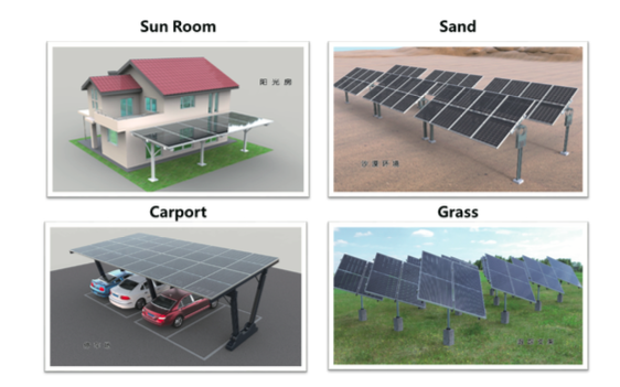
Bifacial modules are widely used in many scenarios. In large-scale power plant projects, bifacial modules generate energy from both side, thus in a longer life cycle for large-scale power plant they can help to contribute more power generation. Moreover, lightweight design of bifacial with transparent backsheet can effectively save BOS cost, thereby reducing LCOE. In desert, snow and other power plant projects, owing to high surface reflectance, bifacial can produce more energy gain.
For distributed project, bifacial modules can utilize limited area to generate more energy and effectively reduce BOS cost, which is applicable for car-port, sun room and so on.
2.Simulation of bifacial module2.1Simulation method of bifacial module
2.1Simulation method of bifacial module
The Bifacial energy gain indicates the additional energy yield of a bifacial module compared with monofacial module.
The Bifacial energy gain is influenced by rear & front side light-absorbing proportion and bifacial factor of modules. The Bifacial factor is the proportion of maximum power of rear-side and that of front-side.
The light-absorbing of the rear side and front side is influenced by albedo, mounting, project location, weather and other environment conditions.
2.2 Albedo
Albedo is the ratio of the reflected light to the global radiation. It is a dimensionless number smaller than 1. Albedo demonstrate the reflectivity of the surface. Different ground type has different albedo. In specific project, albedo is prone to changes in material, thickness, flatness, color and so on. In addition, albedo may be influenced by humidity , seasonal changes , aging, dirt, etc. [3].
Albedo of common ground type is shown in the table below [4]:

Actual project albedo measurement could refer to《ASTME1918-16》, using 2 pyranometers installed horizontally to test the irradiation for both rear & front side. In addition, albedometer shown below is available as well.
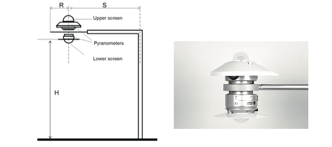
There are some significant points for albedo measurement: (1) measurement instrument should be installed in the plane of array horizontally, and keep the altitude not lower than 0.5m. (2) Avoiding shadings on the pyranometers. (3) Selecting several positions for measurement and averaging the test results to increase accuracy. (4) Long-term review.
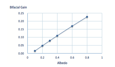
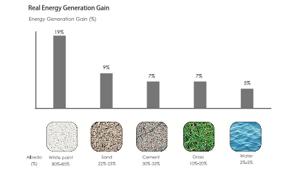
Albedo is the most significant factor for bifacial energy gain. According to PVsyst simulation, bifacial energy gain is in proportional to albedo in figure 14. Real energy gain with different surface type is tested in Jinko Haining field test station, and the results are consistent with the simulation results as shown in figure 15.
2.3 Installation Height
Rear side of bifacial modules does not only receive the reflected light from the ground, but also can collect the ambient scattered light and, in some cases, direct incidence light to produce electricity. Low installation height can affect the irradiance on the backside of the modules which reduces the energy gain. For the fixed installation, the installation height refers to the distance from the ground to the lowest point of the module, as shown in Figure 16(a). For tracking system, the installation height is the distance from the ground to the torque. The bifacial energy gain increases as the installation height increases. Taking the simulation of fixed-installed PV project in Haining as an example, when the installation height is in the low range, energy gain increases rapidly when height increases. When the height exceeds 1.2 m, the increasing speed in the energy gain due to the increase in the installation height is reduced, as shown in Figure 16 (b). The irradiance heterogeneous on the rear side will decrease with the increasing installation height above 1m and the back irradiance becomes more uniform.
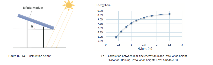
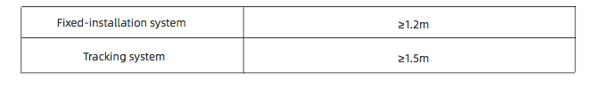
A high installation height will increase the LCOE of the project, so recommended installation heights for fixed-installed and tracking systems are shown in Table 3. For high reflectivity ground (albedo > 50%), the installation height should be appropriately increased.
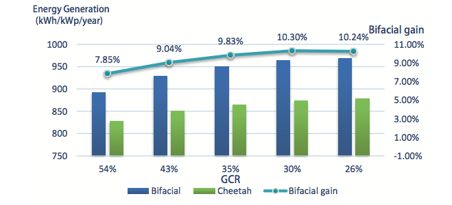
2.4 Ground coverage rate
Ground coverage rate (GCR) is the ratio of module area to land area. When GCR reduces, pitch increases, the rear side of bifacial modules could receive more reflected light, thus generating more energy. For monofacial modules, when GCR reduces, pitch increases and it will reduce the shade, thus increasing energy yield. But the range of the increasing energy yield of monofacial would not be as much as that of bifacial modules.[3]。When GCR reduces, the bifacial energy gain increases as shown in Figure 17.
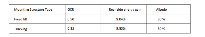
Here are the reference values of GCR for fixed installation and tracking system. Client could decide the pitch based on the project land area and mounting structure design.
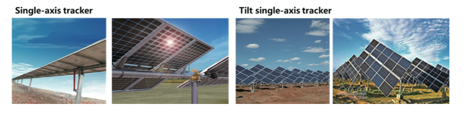
2.5 Fixed tilt or Tracking
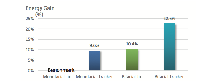
Bifacial module combined with tracking system can achieve more energy gain. The simulation results in Figure 18 (albedo 0.35) show that set the monofacial- fixed tilt type as the benchmark, energy yield of monofacial-tracking type increases by 9.6%; energy yield of bifacial-fixed tilt type increases by 10.4%, and energy yield of bifacial-tracking type increases by 22.6%, which is higher than the simple addition of energy gains owing to the tracking system and bifacial module.
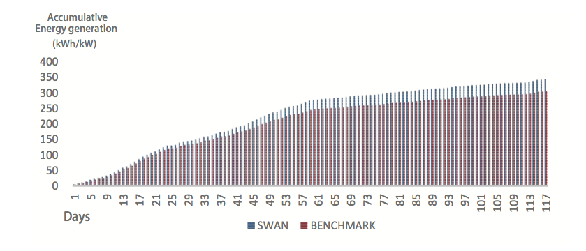
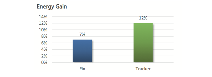
The actual bifacial energy gain from Jinko Haining Field Test Station also reach to the same conclusion. When equipped with tracking system on grass, comparing with monofacial, the swan bifacial has a cumulative generation gain of 12%; while for fixed tilt system on grass, the bifacial energy gain is 7%. Swan bifacial module with tracker could further produce a comprehensive energy gain.
2.6 Frame and rear-side rail shading influence
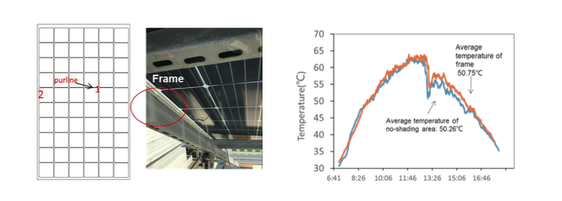
Jinko Swan bifacial module use half-cell technology with specially designed split junction box. The specially designed junction box doesn’t cover the rear-side of cells so as to avoid rear-side shading. The frame shading area takes 2.6%~3.4%, as shown in Figure 25. The temperature on the shading area of frame is very close to the temperature on the area where there is no shading, which proves that frame shading will not lead to hot spot issue.
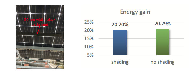
Generally speaking, it is recommended to apply bifacial modules with no-shading mounting system. But in some mounting system, there are rails under the modules. The rail shading can be reduced by adjusting the width and light-reflection of the rail and distance between module rear-side and the rail. On the high albedo ground surface condition, a width of 50mm black backsheet (low albedo) with a distance of 50mm to the module was used to shield the rear-side of module replacing the rail. Bifacial gain is 20.20% when shading, which is only a little bit lower than 20.79% when there is no shading.
When the albedo is lower, indicating that the rail shading has fewer effects in that condition. It is suggested to raise the module more than 50mm higher than the rail to avoid the decrease of energy generation and hot spot issue owing to rail shading.
In tracking system, increasing the distance from torque-tube to module as well as increasing the albedo of torque-tube can decrease the negative influence on the energy generation. Moreover, there are not cells in the middle area (right above on the torque-tube) of half-cell modules, which can also reduce shading on cells.
3 Bifacial System design
3.1 Electricity of Bifacial modules
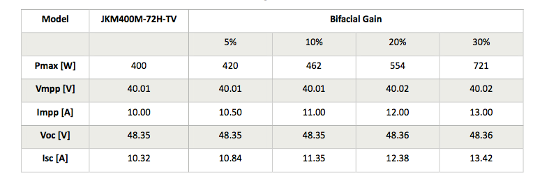
The real electrical characteristics. As a result, it is very important to identify the estimated bifacial gain before selecting the electrical components (inverters, cables, protection devices, etc.). Bifacial gain mainly originates from increasing back-side current, thus the Isc and Impp are proportional to the bifacial gain, and Voc and Vmpp barely change. Take Swan series JKM400M-72H-TV as an example, the electrical characteristics in different bifacial gain are as follows:
3.2 DC/AC ratio and inverter
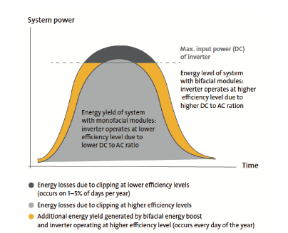
In general, the inverter operates at a lower efficiency in the most time of a year owing to the low irradiance or high environment temperature, as a result clipping loss is unlikely to occur. Bifacial gain will increase the DC end power thus increase the DC/AC ratio, making inverter act under high efficiency. But when DC/AC ratio is high, bifacial module might cause clipping loss. But the clipping loss is less than the energy gain. Therefore, in real PV station design, customer can evaluate the DC/AC ratio through calculation of the optimized DC/AC ratio to reach lowest LCOE.
The DC/AC ratio of bifacial system can be reduced appropriately based on the DC/AC ratio of monofacial module system. The following formula is a reference when design inverter size for bifacial:
DC/AC ratio for bifacial = DC/AC ratio for monofacial / 1+energy gain
Reduction of DC/AC ratio can be realized through increasing AC end size or reducing the module quantities.
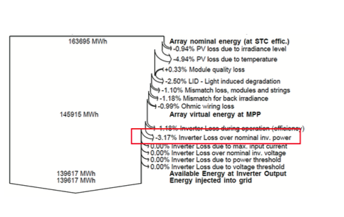
In PVsyst, the clipping loss can be evaluated via “inverter loss over normal inv. Power”, as shown in Figure 28.
Reduction of DC/AC ratio can be realized through increasing AC end size or reducing the module quantities.
In PVsyst, the clipping loss can be evaluated via “inverter loss over normal inv. Power”, as shown in Figure 28.
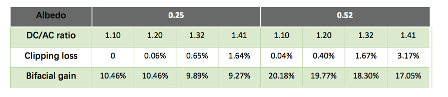
Table 5 shows clipping loss of different DC/AC ratios, based on 105MW project (fixed-installation) in Shandong, China. The increase of bifacial gain leads to increase of clipping loss, and increasing DC/AC ratio also leads to increasing clipping loss, the increasing range will be affected by the project conditions (temperature and irradiance).
Bifacial module energy gain mainly comes from the increase of module current owing to the rear-side energy generation, when operating the module current might reach 12A, so the inverter with higher maximum input current is recommended. Recently mainstream inverter suppliers have improved the maximum input current of their inverters, which can be compatible with bifacial modules.
As to the inverter type, in the mountain area or the area with inhomogeneous albedo, bifacial modules with string inverter can decrease the mismatch loss via multiple MPPT input and control. In the flat area with homogeneous albedo, bifacial modules can be applied with centralized inverter, which can endure high DC/AC ratio and decrease the clipping loss. Customers can choose the inverters and DC/AC ratio according to the actual project situation and the mounting system design.
3.3 Tracking system
As discussion in 2.5 section, bifacial module with tracking system can generate more energy. Jinko swan bifacial modules can be compatible with different tracking systems.
With tracking system, the bifacial module should be installed in vertical direction, in order to keep the mechanical reliability of installation and take advantage of half-cell technology to avoid shading loss. The distance from torque-tube to module should be more than 50mm.
3.4 Mismatch loss of bifacial modules
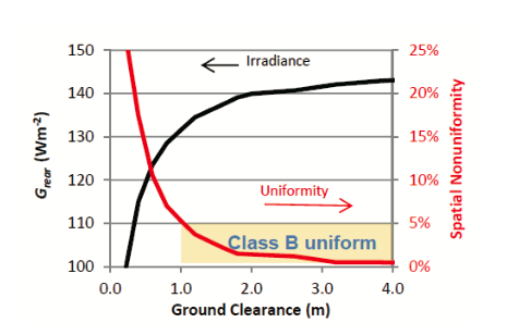
As discussed in 3.2, installation height not only influence the rear-side irradiance, but also have an important effect on rear-side irradiance uniformity. Owing to the rear shading of modules, the cells near the higher edge of modules will absorb more light, while the ones near the lower edge absorb less reflective light. By the same logic, the modules in different lines in an array also have different irradiance uniformity. But when the installation height is more than 1 m, the spatial nonuniformity will decrease to less than 5%[5].
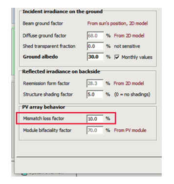
On the other side, the mismatch loss is originated from mismatch of module current (Isc and Impp) due to the irradiance nonuniformity. The mismatch loss is a comprehensive result of the front-side and rear-side energy generation. In real situation (albedo is less than 0.5), front-side irradiance is much stronger than rear-side irradiance, thus the nonuniformity of rear-side irradiance has bare effects on the comprehensive irradiance of both sides. Moreover, the rear-side partial shading (eg., label) also has little effect on the comprehensive irradiance. Even if the albedo is as high as 0.8, the comprehensive irradiance nonuniformity is less than 5%, thus the mismatch loss owing to such nonuniformity is also less than 5%. [6]
Customer can input the mismatch loss in PVsyst (Figure 27) to simulate the bifacial system. The default value is 10%, but according to the research conclusion above, we recommend to use 5% in simulation. As the rear-side irradiance nonuniformity is mainly influenced by the mounting system design, so customer can also refer to the tracker suppliers.
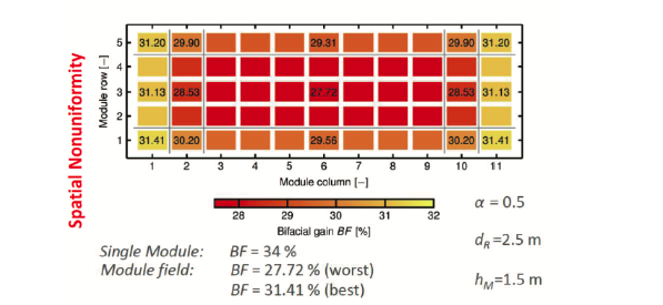
Besides the installation height which causes rear side irradiance nonuniformity, the modules at the edge of an array will absorb more light from the rear side compared with the modules in the middle of array. Therefore module location also influences the bifacial gain, the module at the edge has higher bifacial gain and module in the middle has lower bifacial gain. The difference between highest bifacial gain and lowest bifacial gain is 4%, as shown in Figure 28 [7]. Therefore, the way to minimize loss and maximize bifacial gain is : 1) to make smaller array configuration; 2) to minimize the number of rows in an array; 3) maximize energy generation via MPPT.
4 Precautions on site
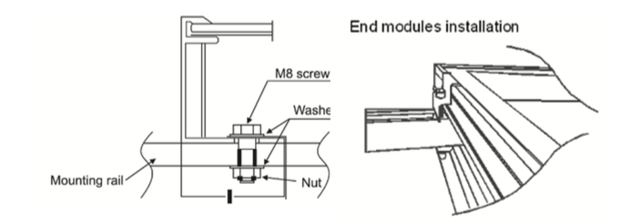
Swan bifacial modules with transparent backsheet can use clamp or screw installation method. Customer can refer to the Jinko “TUV manual”. All special installation and cleaning methods shall be certified or approved by Jinko.
It is better to be cautious that the wires and inverter can cause shading on the rear-side of modules. The ground should be flat and avoid the inconsistency of reflectivity caused by uneven ground, thereby increasing the mismatch loss of the back-side energy generation.
5 Cleaning manual
It is well-known that the accumulation of matter in a surface diminishes with the angle, so the dirt accumulation on the back side of bifacial modules is very slow. According to the field test result in Chile [8], the soiling rate of the rear side is only 11.3% of the soiling rate of the front side. This indicates that the frequency of bifacial rear-side cleaning can be reduced a lot, for example, it is better to clean the front side 4 times a year, but only need to clean the rear side once two years.
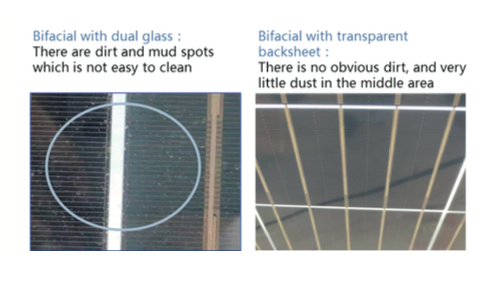
Owing to the stain-resistance of PVF film, which is the outer layer of transparent backsheet, customer can save operation and cleaning cost. The stains on the surface of transparent backsheet are dust and soil which is combined with the backsheet though physical absorption. This kind of stains is very easy to clean by rain, thus the stain is difficult to accumulate on the surface of backsheet and will not have effects on the energy generation. In Jinko Haining field test, there are mud spots formed by mixing ash and rainwater and dried on the surface of bifacial with dual glass, while there is no obvious dirt on the surface of transparent backsheet, as shown in Figure 31.
The clean methods are advised as follows:
a. For the dust on the surface of transparent backsheet, air cleaning (air gun, hair dryer, etc.) or soft brush cleaning can be used.
1.Air cleaning: Choose cold air, do not use hot air to clean the backsheet, 10 cm away from the clean area of transparent backsheet, turn on the cleaning equipment switch, adjust the air pressure to 0.4-0.7 MPa, and clean at a speed of 0.1 m/s, and repeat until the backsheet is clean;
2. Soft brush cleaning: use a soft brush (recommended to use PA612 monofilament soft brush, softness > 70%), gently clean the transparent backsheet with appropriate strength, wiping speed ≤ 1 time /2s (one round back and forth), pay attention to the strength to avoid damage;
b. For the soil on the surface of transparent backsheet, soft brush cleaning can be used.
Soak the soft brush in clear water and wiping dirty area on transparent backsheet with appropriate strength, wiping speed≤1time/2s (a back and forth), until soil is cleaned well.
Reference
1.Dullweber Thorsten,et al. “The PERC+ cell: A 21%-efficient industrial bifacial PERC solar cell”. 31st EUPVSEC. 2015. 2.Pietro Radoia. “Global PV Market Update”. Bloomberg New Energy Finance. 2019.
3.“Bifacial Module Analysis”. Clean Energy Associates. 2018
4.“Bifacial Solar Photovoltaic Module”. Electric Power Research Institute. 2016
5.Chris Deline,et al. “Evaluation and Field Assessment of Bifacial Photovoltaic Module Power Rating Methodologies”. IEEE. 2016.
6.G.J.M. Janssen, et al. “Impact of Inhomogeneous Irradiance at The Rear of Bifacial Panels on Modelled Energy Yield”. European PV Solar Energy Conference and Exhibition EU PVSEC. 2017.
7.J. Libal et al., bifi-PV workshop 2017.
8.Enric Grau Luque, et al. “Effect of soiling in bifacial PV modules and cleaning schedule optimization”. Energy Conversion and Management. 2018.
Statement
This report was written by Jinko Solar Co., Ltd. (hereinafter referred to as “we, us, our, and ours”). This report is based on legally obtained information, but we do not guarantee the accuracy and completeness of such information. Part of the analysis included in this report is based on various assumptions, which may lead to significant differences in the analysis results. The contents and opinions in the report are for reference only.
Copyright of this report belongs to Jinko. Jinko reserves all rights. Without the prior written permission of Jinko, no organization or individual may reproduce, copy, quote or reproduce in any form. Otherwise, the Company reserves the right to pursue its legal liability at any time.