Background
In solar PV systems, circuit breaker selection is something that is easily overlooked and time should be taken to select the correct solution. If the circuit breaker is not appropriate, it will cause frequent tripping of equipment, overheating damage and even system fire. In this Solis article, we discuss how to select circuit breakers in photovoltaic systems.
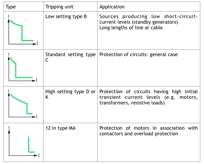
Types of Circuit Breaker
In a PV system, the choice of circuit breaker depends on several factors:
- Electrical characteristics of the system
- Environment
- Loads and the requirements of the installation type
- Ambient Temperature at the Circuit Breaker
For PV systems, equipment is usually installed outdoors (ground mount systems, flat roof systems, etc.). A higher outdoor temperature is usually assumed than for installations in buildings, so it can be expected that the temperature in the distribution board will be higher. This will also affect the flow rate and operating temperature of the circuit breaker.
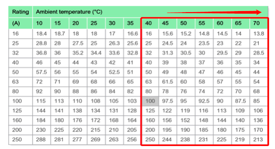
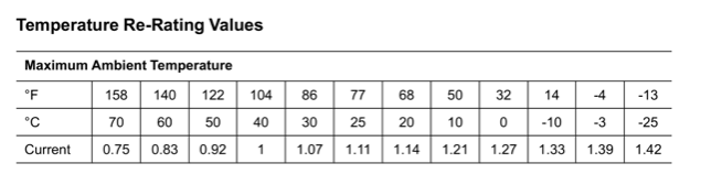
For the selection of circuit breakers in PV systems, temperature is the most important consideration. According to the IEC 60947-2 standard, all circuit breakers have a datasheet detailing the derating/increasing current value of the ambient temperature. You should select the appropriate circuit breaker equipment according to the on-site ambient temperature and the size of the system current.
2. Mutual Heating of Circuit Breakers
For large solar PV power stations with multiple inverters, there are usually multiple circuit breakers in the distribution board, which are closely mounted next to each other. These circuit breakers will provide their maximum current at the same time, therefore the temperature of the circuit breakers will affect each other more quickly, possibly leading to premature tripping.
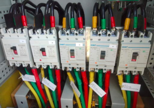
When we install multiple circuit breakers in parallel, we need to consider the correction factor, which is specified in the datasheet of the circuit breaker.
For example, in the case of arranging 6 devices, the correction factor may be 0.75. A circuit breaker with a nominal current of 15.1 Amps (A) behaves like a nominal current of 0.75 x 15.1A = 11.33A.
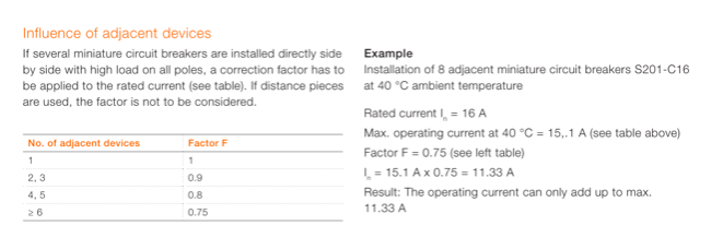
Through this calculation, if the current is insufficient, we can use a circuit breaker with a higher rated current. Another possibility is to increase the clearance between the circuit breakers. This allows more heat to be dissipated, thus preventing unnecessary tripping.
3. Type of Connected Devices
If a PV system is connected to the grid, it will be tripped by the current and voltage impact of the load feeder network. When we choose a circuit breaker, we need to consider the components of the load in this grid in order to choose the most suitable option.
Example System
Examples for the thermal ratings of circuit breakers in parallel operation of PV plant.
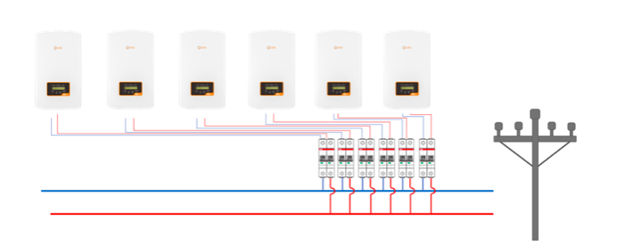
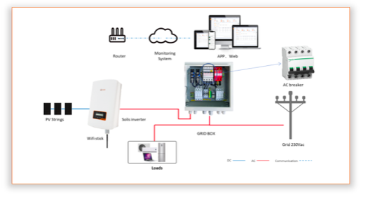
The required technical specifications can be found in the datasheet of the Solis-1P8K-5G inverter:
• Maximum output current = 34.7A
• Its maximum fuse protection = 50A
The choice of cable as well as wiring method, ambient temperature and other potential conditions limit the maximum fuse protection of the cable.
In our example, we assume that the selected cable (6mm²) has ideal routing and can withstand a nominal current of 35A.
The maximum possible nominal current for the cable used and the maximum possible fuse protection of the Solis-1P8K-5G limit the maximum possible nominal current for the circuit breakers.
Selecting the Correct Circuit Breaker
Using the same example system and assuming the load has no motors, transformers etc., based on the calculated current of 34.7A, we choose a 40A circuit breaker with a thermal tripping characteristic of B and no gap between the circuit breakers. We then verify whether our selected value is appropriate by checking the thermal adaptability of the circuit breaker:
The load factor meets the specifications of the datasheet:
•Reduction at permanent load> 1 h = 0.9
(Permanent loads of more than 1 hour are possible in a solar PV plant.)
•Reduction factor when 6 circuit breakers are directly arranged next to each other = 0.75
(If one circuit breaker is used or the distance between each is enough, the coefficient is equal to 1.)
•The increase in nominal current in the distribution board when the ambient temperature is 40°C = 1.0
Result
The nominal load current of the circuit breaker is calculated as:
Ibn = 40 A x 0.9 x 0.75 x 1.0 = 27A
Conclusion
Since the maximum current carrying capacity for fault-free operation is lower than the maximum output current of the inverter used, the selected circuit breaker cannot be used in this example. The circuit breaker will trip during rated operation.
Solution 1
Use a 50A circuit breaker. There is enough space (>10mm) for heat dissipation between the circuit breakers, and the maximum current carrying capacity is 40.5A
(Ibn = 50A x 0.9×0.9 = 40.5A). The circuit breaker will not trip under rated operation.
Solution 2
Use a 63A circuit breaker. Maximum current carrying capacity is 42.5A
(Ibn = 63A x 0.75x 0.9x 1 = 42.5A). The circuit breaker will not trip under rated operation.