The deployment of renewables has been growing at a rapid pace in recent years, reaching record levels, according to IRENA. Among all renewable technologies, solar photovoltaic (PV) power has been dominating the sector for many years.
As PV plant owners channel their efforts towards strengthening the performance and efficiency of their operations, DC cabling selection should not be overlooked. Based on the interpretation of relevant IEC standards and considering factors such as safety, bifacial gains, cable carrying capacity, cable loss and voltage drop, plant owners can now accurately determine appropriate cabling to ensure safe and stable operation across a PV system’s life cycle.
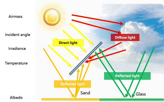
Actual PV module performance in the field is greatly affected by local environmental conditions. The short circuit current given in a module datasheet is based on typical standard testing conditions (i.e. STC: irradiance=1000W/m2, spectrum Air Mass=1.5, cell temperature= 25°C), and does not take into consideration the rear surface current in the case of bifacial modules. Factors such as cloud enhancement, temperatures, irradiance spikes and over-irradiance on the rear surface due to albedo can significantly impact the actual short circuit current.
Choosing the Right DC Cables Is Critical for Both PV Plant’s Performance and Safety
PV plant owners need to make informed decisions when selecting equipment across the whole system to ensure high-performance levels. For example, DC cables are the lifeline for systems, as they interconnect modules to combiner boxes and inverters. Plant owners need to ensure that the size of the DC cable installed is carefully and correctly chosen for the current and voltage of the PV system.
The cables used for wiring the DC section of a grid-connected system also need to withstand the extremes of the environmental, voltage and current conditions under which they operate. This includes the heating effects of both current and solar gain, especially if they are installed close to modules.
The following are crucial areas to be considered when installing DC cabling for solar PV systems:
How to decide on the correct cabling, design and installation
In PV system design, short-term cost considerations can result in poor equipment selection and lead to safety and performance issues in the long run, including potentially catastrophic consequences such as fire. The following areas need to be carefully assessed to meet respective national safety and quality standards:
• Voltage drop limit: Losses in solar PV cabling must be limited, both DC losses in the strings of solar panels and AC losses at the output of inverters. A way to limit these losses is to minimize the voltage drop in cables. In general, a DC voltage drop of less than 1% is desirable and must not exceed 2%. A high DC voltage drop also increases voltage dispersion of the PV strings connected to the same Maximum Power Point Tracking (MPPT), resulting in higher mismatch losses.
• Cable loss: To ensure the energy yield of the PV plant, it is recommended that the cable loss of the entire LV cable (from the modules to the transformer) should not exceed 2% or 1.5%.
• Current carrying capacity: Derating factors which reduce the current carrying capacity of the cables should be taken into consideration, such as the way cables are laid, temperature rises, laying distance and number of parallel cables.
IEC standards for cable selection for bifacial PV Modules
Standards are essential for ensuring the reliability, safety and quality of PV systems, including cabling. Globally, there are several recognized standards for the use of DC cables. Among the most comprehensive are IEC standards.
IEC 62548 sets out design requirements for PV arrays, including DC array wiring, electrical protection devices, switching and earthing provisions. The latest draft of IEC 62548 specifies the current calculation method for bifacial modules.
IEC 61215:2021 outlines definition and test requirements for bifacial modules, introducing solar irradiance test conditions.
Accounting for an overcurrent protection device
An overcurrent protection device is a piece of equipment used to protect against the potentially dangerous effects of overloads, short-circuits or ground faults. The most common overcurrent protection devices are circuit breakers and fuses.
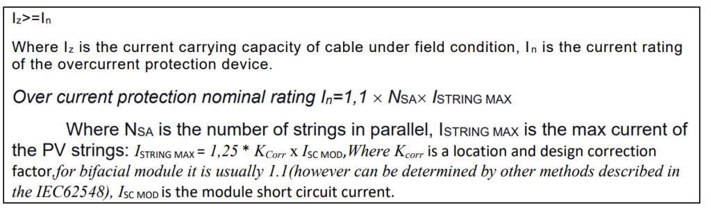
The device will cut off the circuit when the reverse current exceeds the current protection value, so the forward and reverse currents flowing through the DC cable will never be higher than the rated current of the device. In this case, the DC cable should have a carrying capacity equal to the rated current of the overcurrent protection device.
If there is no overcurrent protection device in the circuit, plant owners need to consider the maximum forward and reverse current that may flow through the DC cable and then take the larger value of the two in selecting the correct option.
Accounting for cable installation conditions
When designing and installing DC cabling, it is essential to calculate the current carrying capacity of the cable under certain field conditions to ensure that it is not overloaded. An empirical formula can be used to determine the current carrying capacity of the cable after derating (Iz):

The formula includes various factors affecting the nominal current carrying capacity (I0) including different soil temperatures (f1), multiple cables laid in parallel directly in the soil (f2), soil thermal resistance (f3) and buried depths (f4).
A real life example from the Middle East
Here is a case where a large ground mounted PV power station uses the process outlined to analyze and determine DC cable selection for both safety and performance. The PV array configuration comprises:
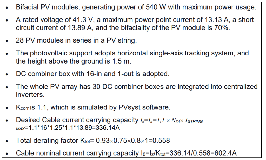
Based on the PV array configuration, the nominal current carrying capacity of the DC cable used in this case should be greater than 602.4A, based on the manufacturer’s datasheet (or according to the cable selection standard IEC60364-5-52, but then the corresponding derating coefficient must also be selected according to the standard.)
The formula resulted in recommendation of two parallel 2×300 mm2 aluminium DC cables from the PV string combiner box to the inverter. The cable length was also reviewed to ensure that the voltage drop of the cable and total cable losses met specified project requirements. To ensure that the DC voltage drop is less than 2%, the specifications for certain long-distance cables should be increased from 2 x 300 mm2 to 2 x 400 mm2. At the same time, it should be noted that the cable laying coefficient will be further reduced when two cables are laid in parallel.
We can see that, due to radiation, temperature rises, gain at the rear of the bifacial modules and the derating coefficient of cables, DC cables with a thicker diameter will need to be applied, which increases cost. With the purpose of controlling cost and ensuring plant safety, the DC cable length should be shortened or the DC current should be limited by power electronics equipment, such as string inverters.
The importance of PV equipment selection and inverter configuration
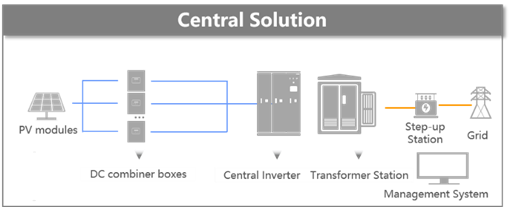
In the configuration of a central inverter, multiple PV strings are connected in parallel to a DC combiner box, with multiple combiner boxes connected in parallel to the inverter.
Therefore, the maximum output current at the combiner box and the input current at the inverter are constantly varying and of significant uncertainty. There are safety risks and additional design margins that must be considered during selection of electrical equipment (fuses, disconnectors, cables in PV subarray and PV array), which will significantly increase the final balance of system cost.
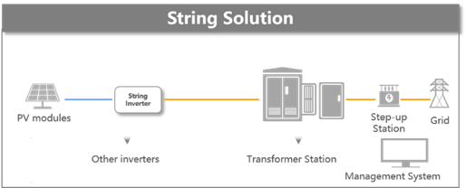
In contrast, a string inverter solution will convert the fluctuating, uncertain energy on the PV side into a controllable electricity output. The inverter limits the current output, thus the diameter of the inverter output cable does not need to consider changes in light, temperature or bifacial modules. This allows designers to select the most cost-effective cables and overcurrent protection devices for their projects. Moreover, string inverters have a shorter DC cable and lower DC voltage drop, inherently resulting in less mismatch loss and more electricity generation.
In conclusion, unlike conventional energy, the operating current of a photovoltaic module is greatly affected by environmental conditions and bifacial gain. These factors need to be fully considered in the cable selection process during the design phase, along with appropriate restrictions on voltage drop and cable losses, to ensure the long term ROI of a PV plant.