The rapid advent of the high-power module era has made the industry acutely aware of the new challenges presented by module technology. Based on the concept of maximizing customer profit at the system side, module product design is now gradually shifting toward the direction of large current. However, when module current increases to a certain level, it may bring with it some natural risks that cannot be ignored, together with the problem of power generation loss. These issues must be addressed by the industry, especially when it comes to quality and electrical safety risks involving products and systems.
The Birth of Large-current Modules
Levelized cost of electricity (LCOE) is a core indicator for evaluating PV projects, with the impact of efficiency, power and power generation performance on the module side critical to its reduction.
In 2009, the leading module power in the PV industry was only 290W. After more than a decade of development, this has risen to over 500W, with some modules now exceeding 600W. There are several methods of increasing module power, such as improvement in conversion efficiency due to solar cell technology advances and the optimization of module layout and auxiliary materials. Increase in wafer size has also played a significant role. Initially, mass-produced solar cells were designed and manufactured based on 125mm wafers, which later developed into 156mm, 156.75mm, 158.75mm and 166mm wafers, and from there to the current 182mm and 210mm wafers. The emergence of large size wafers, particularly those of 182mm and 210mm, directly drives module power to a new level, also significantly improving operating current.
Generally speaking, the internal logic of the wafer size increase has two main points: on the one hand, it can effectively reduce the cost per watt of silicon wafers and solar cells, also lowering module production costs; on the other hand, increasing module power through increasing wafer size can effectively reduce system-side BOS costs. Nevertheless, any kind of enhancement must be achieved within certain parameters, with cell size and current increases beyond a certain level carrying potential risks which may outweigh any gains.
Production and Quality Risks
In the production process, as cell size increases, product yield will decrease due to the increased complexity of production. The product yield of large size wafers and cells may be difficult to match that of the original product in the initial production stage, and certain problems brought about by the increase in size may not be completely resolved even as the process matures. At the same time, oversized wafers will affect the application of thinner wafers and increased module size is not conducive to a cost reduction in frames and glass, these two considerations having an impact on production costs. In addition, increases in wafer and module size can bring the following negatives: an increase in the risk of mechanical load on the module, potential difficulties in handling and installation, a demand for higher load bearing capacity of the rack, and the effect on product and system quality during the whole life cycle.
The Effect of Large Current on Power Generation
1. Power loss
We conducted a comparative analysis of the DC loss of PV cables for a 182 module (Imp ~ 13A) and a super-large current module B (Imp ~ 18A) based on 100MW projects. Under STC, the DC loss of the project with super-large current module B was approximately 0.2% higher than that of the project with the 182 module due to the higher current, while using the same 4mm² cable. Even when assuming the actual solar irradiance to be 70% of the STC, the difference in DC loss between the two projects was still about 0.14%. In PV systems with bifacial modules, the difference in DC loss will be even larger, because the operating current of bifacial modules may increase by 10% to 20% compared to monofacial modules.
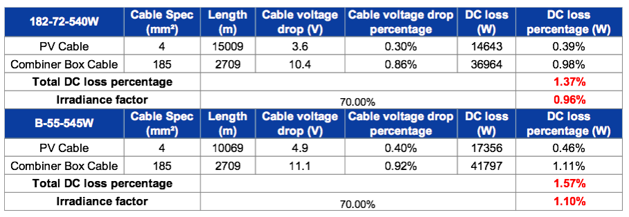
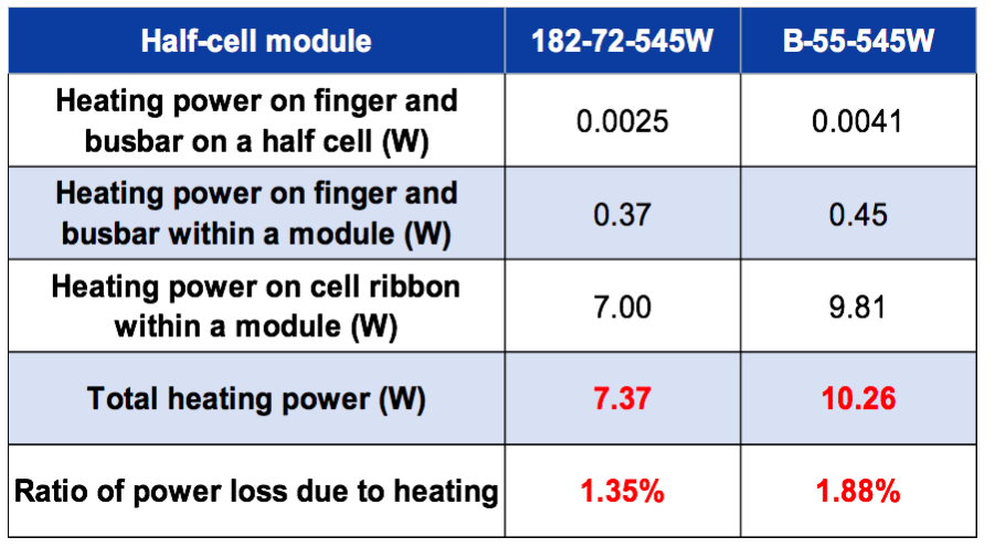
In terms of heat loss within the module, we have also conducted relevant research and calculation. The results show that the heat generation on the cell ribbons is more obvious compared to the heat generated on the fingers and busbars in solar cells. The heat loss with super-large current module B is 0.53% higher than that of the 182 module. If we take a 3GW project as an example, because of the direct heat loss, the super-large current modules will generate 20 GWh less electricity than 182 modules per year.
2. Estimated power generation and LCOE
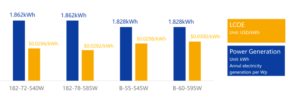
Simulation results show that the power generation of 182 modules is 1.862 kWh/Wp/year which is 1.8% higher than that of super-large current modules. In terms of LCOE, 182 modules present an LCOE of $0.0292/kWh which is 0.04-0.08 cents/kWh lower than that of super-large current module B.
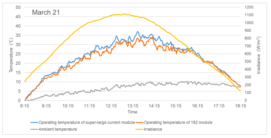
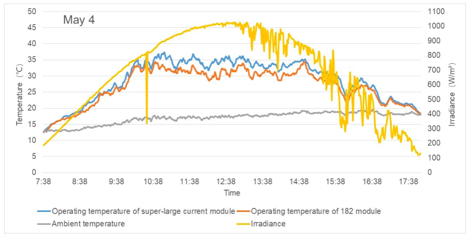
3. Plant performance demonstration
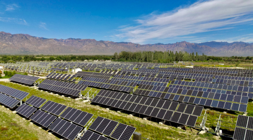
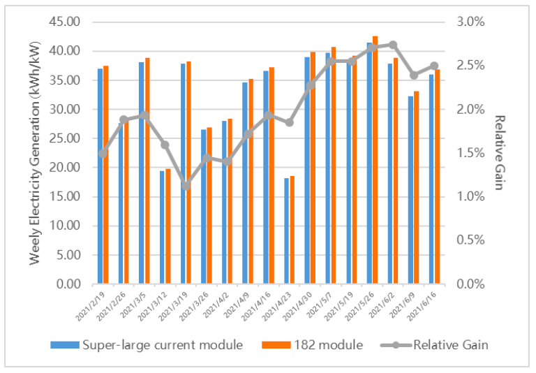
In order to fully investigate the difference in power generation performance and operating temperature of different modules, JA Solar and TÜV NORD conducted a comparative study on the power generation capability of a 182 module and super-large current module at the Yinchuan National Photovoltaic Experimental Base from February 2021. It can be seen from the diagrams that, on a sunny day, the average operating temperature of the super-large current module is 1.8°C higher than that of the 182 module, with the maximum temperature difference potentially reaching 5°C. The main reason for this is that excessive working current of a module will lead to significant increase in heat losses on the metal contact of the solar cell and the cell ribbon, which will increase the working temperature of the module to a certain extent. It is known that the output power of a PV module decreases with the increase in temperature, and each degree-Celsius of increase in working temperature will make the power decrease by about 0.35%. Meanwhile, it can be seen from data from the demonstration system, with the influence of various factors, that the average energy yield per watt of the 182 module is about 1.8% higher than that of the super-large current module.
Electrical Safety Risks
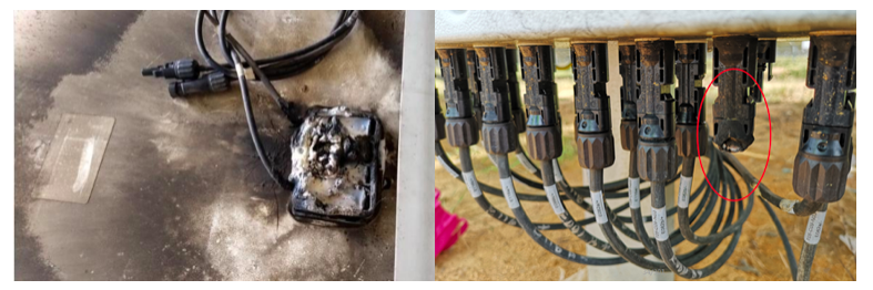
PV modules are assembled with solar cells plus extra EVA or POE, backsheet, and glass. The DC current generated by a PV module flows through the junction box, cable and connector. In the whole system, the junction box and connector are small parts that do not attract attention. However, if there are problems with these two small parts, there will be huge safety risks. According to third party industry statistics, most PV system failures (especially fire) caused by the PV module are related to the junction box and connector. Therefore, in the process of module design, junction box selection is a vital technical consideration, especially for large-current modules, where the current carrying capacity of the junction box diode is critical.
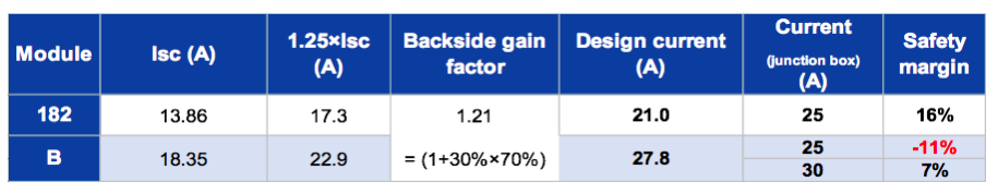
To ensure the current-carrying capacity of the junction box diode, it is recommended that the rated current of the junction box should be greater than 1.25×Isc (short-circuit current) for monofacial modules. In terms of bifacial modules, we should also consider 30% bifacial gain as well as approximately 70% bifaciality. A 25A junction box, which is very mature in the market, can be used for 182 bifacial modules to achieve an adequate safety margin of about 16%. This fully guarantees the reliability of the long-term operation of a 182 module. A module with higher current will require a junction box with a higher rated current of 30A. It can be seen from the table below that, even if a 30A junction box is adopted, the safety margin for super-large current module B is still lower, and the risk of overload in environments with high irradiance and high temperatures is somewhat increased.
As for PV cables, we have studied and calculated the current carrying capacity of those based on the IEC 62930 standard. In a typical ground-mounted or distributed rooftop PV system, the current-carrying capacity of 4 mm² cables is sufficient for both 182 and super-large current modules. However, when the temperature reaches 70°C on certain distributed rooftops, for super-large current modules there may be risk of overheating, burnout of cables and fire hazards, unless 6mm² cables are used.
System-side Hardware Compatibility
When large-current modules were first introduced to the market, there were some current matching problems between string inverters and super-large current modules. However, companies including Sungrow, Huawei, Sineng and GoodWe have now launched string inverters suitable for super-large current modules, meaning that there are no longer issues on the system side.
The Future Direction of Module Design
While looking to develop high-power modules, we need to consider not only power generation performance in the field, but also how to ensure excellent reliability to guarantee customers’ long-term profitability. According to technical analysis, under existing conditions further increases in module size and current will not necessarily achieve lower system costs – indeed, there can be a significant decrease in power generation performance and an increase in safety risks. Therefore, the focus for the industry in the future should be switched towards efficiency and energy yield improvement via technological progress.