1. Background – Evolution of PV Silicon Wafer Size
Two aspects need to be considered in the evolution of the size of PV silicon wafers: the influence of wafer size change on manufacturing costs in the industrial chain and the influence of wafer size on module size, electrical parameters and module application at the system side.
In early times, PV cells were similar to semiconductor chips, with equipment and process costs relatively high. Thus, increasing wafer size could significantly reduce the manufacturing cost of cells. As the PV industry has become more mature, the situation has changed. Today, the cost of manufacturing solar cells is about $0.03/Watt, which represents a dozen-fold reduction; silicon wafer / cell size has also evolved independently to include M1 (156.75-φ205mm), M2 (156.75-φ210mm), M4 (161.7-φ211mm) and other specifications, while wafer thickness continues to reduce.
While the PV industry’s mainstream wafer size remained stable at 156.75mm for several years, new sizes of G1 (158.75-φ223mm) and M6 (166-φ223mm) then emerged. On the one hand, these slightly larger wafer sizes were compatible with existing cell and solar glass production lines to enable immediate cost savings. On the other hand, the module size increases of less than 10% meant that the original M2 module could be replaced in all applications, and BOS costs could be saved to a certain extent where the original boundary conditions remained unchanged at the system side.
With the rapid capacity expansion of the PV industry chain, manufacturers then considered new sizes beyond the compatibility of existing production lines. Some manufacturers introduced 12” silicon wafers, G12 (210-φ295mm), which matched the semiconductor chip, aiming to further reduce cell manufacturing and system costs through high-power modules of larger sizes. The reason behind the choice of the M10 (182-φ247mm) size is that, unlike the semiconductor industry chain, the manufacturing cost of PV cells is not the core factor to consider for size change due to its low proportion of the overall industry chain cost; the boundary conditions for design and application of PV modules need to be considered comprehensively, so that wafer size shall be based on optimal module size. After an in-depth analysis of the whole industry chain (manufacturing, transportation, installation, power generation performance and system matching), M10 (182-φ247mm) was introduced.
(Note: The 12” semiconductor silicon wafer is 50μm thicker than the 8” silicon wafer, and it never replaced the 8” silicon wafer, being mainly used for chips ≤ 28nm to lower chip processing cost)
2. Design Idea – Boundary Conditions for Module Size
• Packaging and transportation of modules
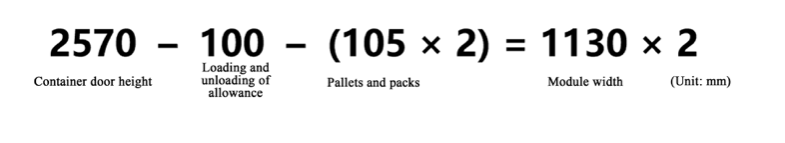
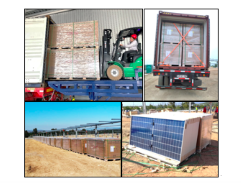
PV modules are usually packaged vertically in landscape orientation to ensure stability and minimize damage during transportation. If lying flat, weight and vibration during transportation will likely result in µ-cracks and damage to the modules. If packaged vertically in portrait orientation, stability is compromised and the risk of tipping over is much higher, posing significant challenges during unpacking. In the 40HC container commonly used for overseas shipments, double stacking of pallets is common practice, so the height of the two pallets of modules cannot exceed the container door height of 2.57m. In addition, considering surface undulation on the project site, it is necessary to leave about 10cm of operating margin for forklift unloading, and the width of modules is limited to about 1.13m. With a typical 6 row module layout, the width of each cell and wafer is limited to 182mm.
• Manual handling and installation of modules
Within a certain range, the size and weight of PV modules can be increased to reduce manual handling and installation costs on a per Watt basis. Beyond a certain limit, manual installation will become more difficult, as workers are prone to fatigue and breakage rate during installation will be significantly increased.
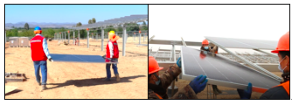
The width of PV modules used to be about 1m, meaning that installation workers could hold them between open arms. With module width increased to about 1.13m, two people can still move them stably on a flat terrain. However, module width should not be increased further to avoid compromising stability during handling.
The weight limit for frequent handling by a single person is approximately 20-25kg, and the weight limit for two persons is not simply multiplied by 2, but by a coefficient of 0.666, giving the following formula:
25kg×2×0.666=33.3kg<35kg
For this reason, module weight should be controlled within 33.3kg, and maximum weight should not exceed 35kg. The 72c-182 bifacial double-glass PV module weighs about 32kg, which can be handled and installed easily by two people in almost all scenarios except for rugged mountainous regions, thus saving labour costs when compared with the current mainstream 72c-166mm wafer size module.
• Load capacity of module
The primary factor determining the load capacity of PV modules is glass, followed by the frame. In consideration of module cost and weight control, the glass thickness of a bifacial double-glass module is preferably 2mm. On the premise of a 2 + 2mm double-glass structure and reasonable control of frame cost, module size should be within a limit, otherwise the ability to resist static and dynamic load will be seriously weakened. Under laboratory testing and outdoor application conditions, frame damage, glass burst and large quantities of micro-cracks are prone to occur, leading to excessive degradation in module power throughout the product’s lifetime.
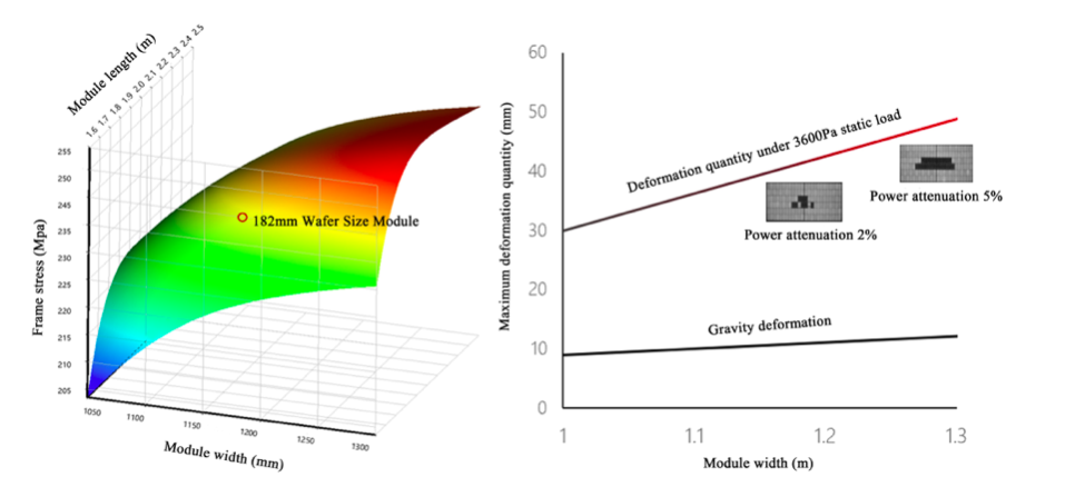
Based on theoretical analysis, the frame stress of a 182mm wafer size module is within safe parameters under load (the left image in Figure 3 shows the frame stress simulation under 5400Pa load). Obviously, an increase in width leads to a greater stress level than that brought about by an increase in length. Under a static load of 3600Pa with no beam installed on the back, a module of 1.13m width has lower deformation, and its power degradation is less than 2%. Therefore, from the perspective of risk control on investment return from a PV power station, module size, especially its width, should not be further increased.
3. Product Profile
• Dimensions, weight, electrical parameters
Based on the above analysis, and considering the limitation of module size and weight, the classical half-cut module design is still adopted, and the side length of the 182mm silicon wafer can be deduced. The area of a 182mm (M10) wafer is 330.15cm2, 20.4% larger than that of a 166mm (M6) wafer of 274.15cm2. Thus, we find that the area, weight and current of the module are increased correspondingly. Typical parameters of 72C 182mm and 166mm wafer size modules are listed here:
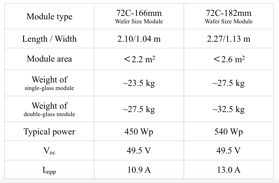
It can be seen that the 182mm wafer size module provides an optimal solution for large-scale utility photovoltaic power stations due to its relatively reasonable size and weight.
• Mass production
A 182mm wafer size module is a standard-sized product designed for the new capacity of cells and modules, which breaks through the limitation of existing capacity compatibility and has the largest common divisor, after 166mm, in the industry. By the end of 2021, LONGi, Jinko and JA will each establish at least 30GW of production capacity for 182mm cells and modules. Total capacity for 182mm wafer size modules for the whole industry will be more than 100GW.
The first batches of 182mm wafer size modules have been mass-produced and supplied during Q4 in 2020. A higher level of industry chain maturity is maintained due to module size variations being less than 20%. The silicon rod and wafer maintain the same manufacturing yield as the 166mm wafer; the cell conversion efficiency and yield of the 182mm cell also reach the same level as the 166mm product; the mass production power of a bifacial module is 535 / 540Wp, and its loading capacity and hot spot temperature are both within the recommended safety parameters.
• Industry chain compatibility and product standardization
The 182mm wafer size module experiences some change in size and current, which sets new requirements for BOM support at the system end.
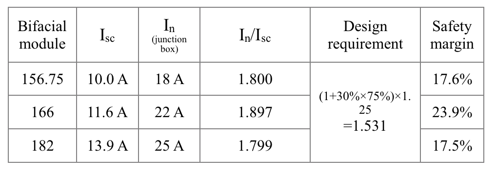
In terms of BOM, the new PV glass manufacturing and deep processing capacity can be compatible with 1.13m wide glass, and there is no problem with the supply of encapsulants and backsheets; due to the current increase of about 20%, the 182mm bifacial module uses a junction box with a rated current of 25A (the junction box uses 3 large-size bypass diodes), which maintains sufficient safety margin and fully guarantees reliability over long-term operation with large current.
The system side mainly involves the matching of string inverter and horizontal single-axis tracking system. Assuming a bifacial gain of about 15%, a bifacial module with an Imp of 13A needs to adopt a 15A string inverter, which can be achieved via a minor adjustment to the previous mainstream 13A string inverter, without changing the core IGBT chip. The product can be downward compatible with 166mm and other specifications of module, thus avoiding the risk of product fragmentation and core element change.
Length and width of a 182mm wafer size module are each increased by about 9%. Trackers can support modules with the same number of strings by means of moderate structural strengthening, with the increase in total power of the module reducing the support cost per watt. At present, mainstream 1P and 2P trackers are compatible with 182mm modules but, as described in Section 2, it is not advisable to apply wider modules on trackers (especially 2P trackers) after taking into account possible module deformation under wind load and power degradation due to cracks.
4. System-side value
The BOS cost saving with high-power modules is realized mainly in 3 aspects: A-The larger racking design is adopted to improve the total power of modules carried on the single rack, so as to reduce the support and pile foundation costs per Wp; B-The total length of cables connecting strings and combiner boxes (or string inverters) is reduced with the increase in string power; C-Module size is moderately increased to reduce labour costs.
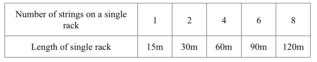
For a power station in a hilly region with serious terrain undulation, the length of a single rack is limited and it is difficult to move large modules. Therefore, the 182mm wafer size module is mainly applicable for relatively flat terrains. Costs can be significantly reduced by combining the design of ultra-long racking with the optimized spacing of pile foundations. For fixed racks, the length of a single rack will be limited to about 120m due to the thermal expansion and contraction of steel. The 182mm module is compatible with the two row design of vertical (2P) and four row design of horizontal (4L) racks, and can adapt to different terrain conditions by adjusting the number of strings on a single rack. The typical length of a 2P fixed rack is shown in the following table (calculated based on 26 182mm modules per string):
Similar to fixed tilt racking, there is a restriction on the length of the tracker. Further increases in module size and string power will reduce the number of strings on a single tracker, but cannot improve the total power carried by the tracker, so cannot save on costs in this area.
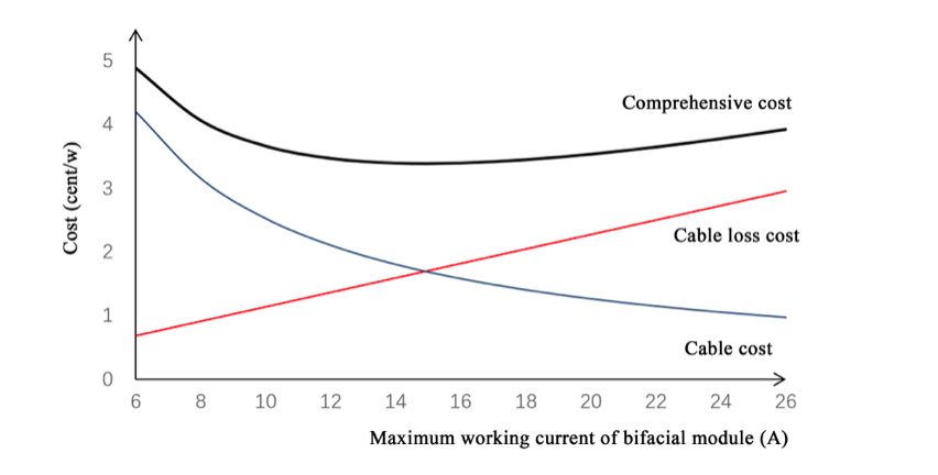
In terms of cable costs, as shown in Figure 5, with the increase in module current and string power, the cost of 4mm2 cabling is gradually reduced, yet costs incurred due to cable power loss increase on an almost linear basis. Taking these two costs into consideration, the current at the optimal cost point is about 14 ~ 15A, that is, the working current of a 182mm bifacial module. Additionally, cable costs will be further reduced once the two channels of strings are converted into one channel and then connected to the combiner box (or string inverter) by a 6mm2 cable.
In terms of labour costs, as described in Section 2, there is a limit to the weight of a module when handled and installed by two persons. Beyond that, people are prone to feeling fatigued due to long working hours, thus efficiency will be compromised and breakage rates during installation potentially increased.
Based on the above, the BOS costs of a PV power station have been compared and analyzed under fair boundary conditions. The results, verified by TÜV NORD, are as follows (the difference in manual installation cost is not considered):
(Conditions: Wind pressure 0.38kN / m2 [25 years], 0.45kN / m2 [50 years]; snow pressure 0.21kN / m2 [25 years], 0.25kN / m2 [50 years]; inclination 34°; the lowest point of the module is 1.5m above the ground; the land cost is calculated based on $ 0.127 / m2 / year and a lump sum payment for 20 years)
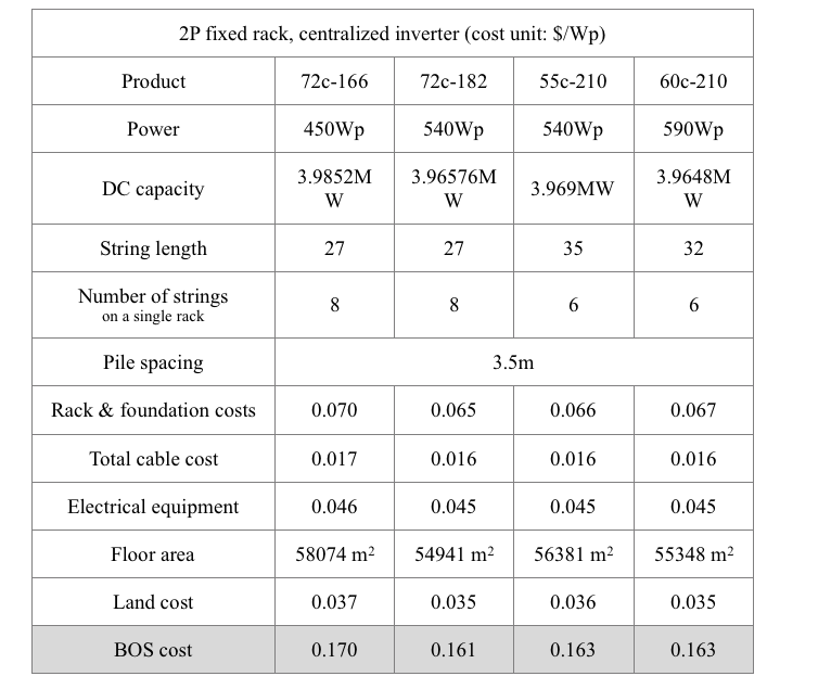
The calculation results for the 2P fixed rack meet expectations: the 182mm module has an obvious advantage over the 166mm equivalent in terms of BOS cost; compared with 60c-210 and 55c-210 modules, there is little difference, but with a slight advantage due to the higher efficiency of the module; in the case of vertical installation, the BOS cost of the 60c-210 module is lower than that of the 55c-210 module, because the longer module has a slight advantage in both racking and foundation costs.
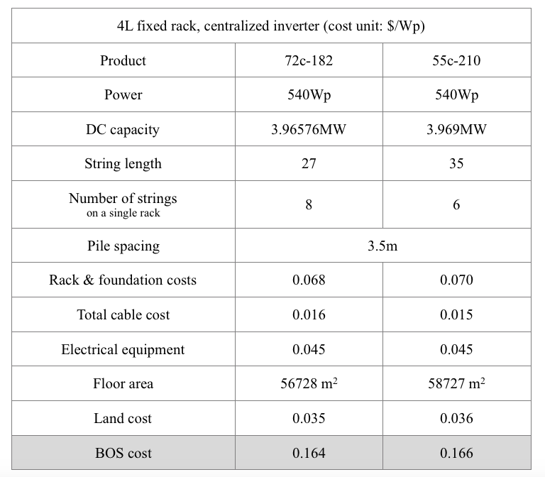
The BOS costs of a 182mm module and a 55c-210mm module installed on a 4L support are further compared below. The results show that the former has a slight advantage in racking, foundation and land costs due to higher efficiency. Excessively wide modules are not considered for comparison due to poor loading capacity when there is no beam, and difficult installation of the top row of modules in the case of a 4L rack.
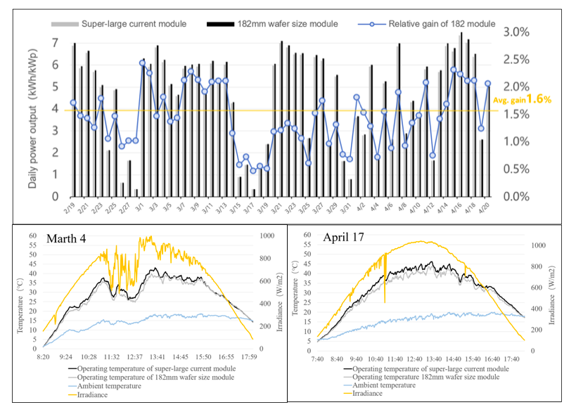
Excessive working current of a module will lead to a significant increase in heat losses on the metal contact surface of the cell, ribbon and bus bar, which will increase the working temperature of the module to a certain extent. This has been proven by comparison and analysis of the working temperatures of half-cut and full-size modules. JA and TÜV NORD conducted a comparative study on the power generation capability of a 182mm module and a super-large current module in the Yinchuan National Photovoltaic Experimental Base, and the data for two months (from February 19 to April 20, 2021) can be seen in Figure 6. On a sunny day, the average operating temperature of the 182mm module is 1.7℃ lower than that of the super-large current one, with the maximum temperature difference as high as 4~5℃. Meanwhile, the average energy yield per watt of the former is about 1.6% higher than that of the latter, thus the 182mm module shows an obvious advantage in power generation.
In addition, at TUV Rheinland’s 7th (2021) All Quality Matters (AQM) Solar Congress, 182mm modules from JA and LONGi respectively won the Energy Yield Simulation award – Mono Group (Monofacial) and the Energy Yield Simulation Award – Mono Group (bifacial) to further prove their excellent power generation performance (TÜV Rheinland had tested the Pan files of 5 modules from a mass-produced 1,000 modules to simulate power generation at 5 locations around the world).
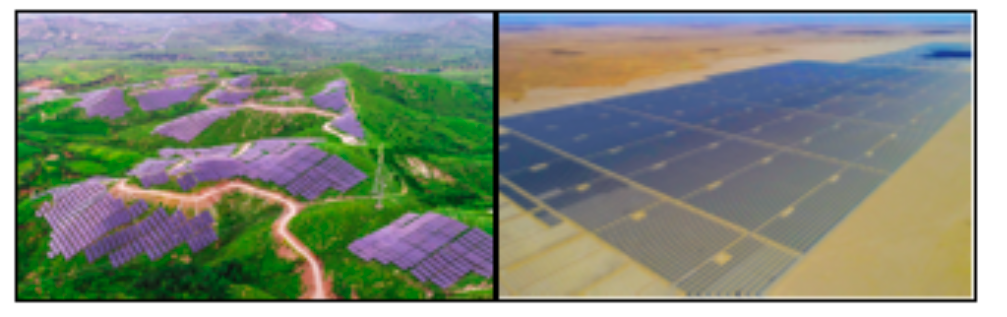
5. Application Cases
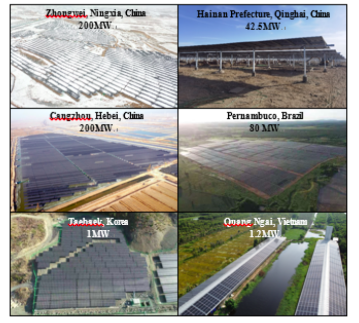
in Different Scenarios around the World
6. Summary
PV power stations are designed to work reliably for >25 years, being able to perform well even in extreme weather conditions. Reliability of both module and system is the basis for ensuring return on investment and realizing value for customers. The 182mm wafer size module is the most cost-effective solution based on in-depth analysis of various boundary conditions within the whole industrial value chain. Without efficiency improvement, further increases in power from larger size modules will not necessarily achieve lower system costs – indeed, there is a significant increase in reliability risk with oversized modules. Simply increasing module power based on larger and larger dimensions is not technological innovation. Instead, a standardized module size can help switch the focus of the entire industry value chain (manufacturing equipment, bill of materials, inverters, trackers) towards efficiency and energy yield improvement.