The risk of flooding to and from solar projects is a growing challenge for the PV industry worldwide. Drawing on his experience of flood risk engineering for utility-scale solar projects in the US, Hossein Ghoveisi makes the case for early, accurate hydrology in solar project design.
Civil engineers have long understood one fundamental truth: water doesn’t negotiate. It finds the lowest point, fills available space, and rarely behaves exactly the way a desktop model predicts. For utility scale solar developers, this reality is becoming increasingly difficult to ignore.
Try Premium for just $1
- Full premium access for the first month at only $1
- Converts to an annual rate after 30 days unless cancelled
- Cancel anytime during the trial period
Premium Benefits
- Expert industry analysis and interviews
- Digital access to PV Tech Power journal
- Exclusive event discounts
Or get the full Premium subscription right away
Or continue reading this article for free
A combination of shifting watershed dynamics, more intense storm events and a shrinking supply of low risk development land is pushing flood risk management from a back end permitting concern to a front end design priority. The gap between developers who recognise this shift and those who don’t is widening with every construction season.
The consequences of getting it wrong are significant in both directions. A solar array inundated during a 100-year storm event which, over a 30-year lifespan, has roughly a 30% chance of occurring—can suffer structural damage to racking systems, tracker mechanisms, inverters and cabling. The resulting repairs can be costly and, in severe cases, catastrophic to project economics.
But the reverse risk is equally important, and frequently overlooked. A large solar development substantially alters the hydrology of its surrounding landscape. Improperly managed grading and drainage can increase runoff volumes and velocities across adjacent land, threatening downstream infrastructure, neighbouring properties and the communities that permit these projects. Regulators and insurers are increasingly aware of both risks and asking harder questions earlier in the development process.
Flood risk also extends beyond the operational phase of a solar facility. Construction activities temporarily disturb soil and alter natural drainage pathways, increasing the potential for erosion and sediment transport during storm events. If stormwater controls are not properly designed, runoff from construction areas can affect nearby waterways and create regulatory compliance issues.
In addition, solar projects typically operate for 30 to 35 years, requiring them to stay resilient through decades of changing watershed conditions. Land development upstream, infrastructure deterioration downstream, and shifts in precipitation patterns can all change flood behaviour over the life of a project. Designing for current conditions alone may not fully capture these long-term risks.
Understanding why flood risk is escalating—and how to mitigate it—requires thinking well beyond the fence line.
The technical challenges of flood risk for PV design
Watershed dynamics: why the site boundary is the wrong frame of reference
One of the most persistent misunderstandings in solar flood risk assessment is treating it as a site-level problem. In my 15 years as a hydrologist working on major civil projects, I have learned that flood risk is fundamentally a watershed issue.
A watershed includes the entire catchment area draining to a given point, including upstream land uses and downstream infrastructure. These elements determine flood behaviour at a project site—and they change faster than many modelling datasets reflect.
Upstream development is one of the primary drivers of changing flood risk. Activities such as urban expansion, new road construction and land use conversion reduce natural infiltration and accelerate the movement of stormwater into drainage channels. A forested catchment that once absorbed most rainfall may, after development, behave more like a hard surface basin.
When permeable soil and vegetation are replaced with rooftops, parking lots and roadways, stormwater moves downstream more quickly and in greater volumes. Peak flows rise, runoff arrives earlier and downstream infrastructure faces higher stress.
Despite these shifts, many developers still rely heavily on Federal Emergency Management Agency (FEMA) floodplain maps as the baseline reference for site analysis. While these maps remain an important regulatory tool, many are outdated. In active development regions, some FEMA floodplain maps date from 2012 or earlier. In rural areas, maps from the 1980s sometimes remain the most recent available versions.
Downstream infrastructure presents an equally complex challenge. Water ultimately exits watersheds through culverts, channels and road crossings that were designed for specific storm frequencies decades ago. As rainfall intensity increases and upstream land use changes, these structures often become undersized.
The American Society of Civil Engineers currently grades US infrastructure overall at a ‘D’, and inadequate culverts contribute significantly to that rating. Sediment accumulation, partial structural failure and deferred maintenance can all reduce a culvert’s effective capacity well below its design specification.
When these structures back up, water levels rise upstream. This backwater effect can inundate project infrastructure that was originally modelled at a lower base flood elevation.
Watershed dynamics, not parcel boundaries, ultimately control flood behaviour. Ignoring that reality can expose projects to risks that no amount of site-level drainage design can fully mitigate.
Predictive tools and modelling techniques
Identifying flood exposure before it becomes a field problem requires hydraulic and hydrological modelling that extends beyond the project boundary.
The industry’s standard tools—HEC RAS for hydraulic modelling and HEC HMS for watershed hydrology—are well established and widely trusted. However, the reliability of these tools depends entirely on the quality of the data used to build them. A model built using outdated land use data, or coarse terrain information, can produce results that appear precise while failing to represent current flood behaviour.
Reliable modelling requires comprehensive input. High-resolution LiDAR terrain data is essential for accurately defining watershed boundaries and surface flow paths. Updated satellite imagery and land use maps help capture recent development that may have altered runoff patterns. Rainfall data from current databases, such as Atlas 14, provide updated precipitation statistics, while municipal or county records provide crucial information on culverts, road crossings, canals and spillways.
For large utility scale solar projects covering hundreds or even thousands of acres, watershed scale modelling is often the only practical way to understand how relatively small changes in grading or drainage infrastructure can influence flood behaviour across the entire site.
In addition to HEC RAS and HEC HMS, engineers frequently use culvert analysis software such as HY 8, developed by the US Federal Highway Administration. HY 8 allows designers to evaluate culvert capacity, headwater elevations and potential backwater effects at roadway crossings. Because culverts often represent hydraulic control points within a watershed, accurately modelling their performance is essential when predicting flood elevations at solar sites.
Hydrologic and hydraulic (H&H) modelling also plays an important role in developing erosion and sediment control strategies. By analysing runoff velocities, flow depths and shear stresses, engineers can identify locations where erosion may occur and where stabilisation measures such as erosion control blankets, riprap armouring to absorb floodwater’s kinetic energy, check dams, or vegetative reinforcement may be required.
For solar projects, these analyses are particularly valuable along access roads, drainage swales and perimeter channels where concentrated runoff is most likely to develop.
| Tool | Primary function | Key inputs |
| HEC-RAS | Hydraulic modelling: simulates water surface elevations, flow velocities and flood extents through channels, culverts and floodplains | LiDAR terrain data, culvert dimensions, road crossing elevations, channel geometry, Manning’s roughness values |
| HEC-HMS | Watershed hydrology modelling: calculates runoff volumes, peak flows and timing from rainfall events across a catchment | Watershed boundaries, land use and soil classifications, rainfall data (e.g. Atlas 14), antecedent moisture conditions |
| HY-8 | Culvert analysis: evaluates culvert capacity, headwater elevations, and backwater effects at roadway crossings | Culvert dimensions, inlet/outlet geometry, tailwater conditions, design storm frequency |
| GIS/LiDAR processing | Geospatial analysis: defines watershed boundaries, maps surface drainage paths, identifies ponding areas and processes terrain data | High-resolution LiDAR point clouds, satellite imagery, updated land use maps, infrastructure records from municipal/ county sources |
Integrate hydrology and grading early
Grading and hydrology are closely interconnected. The final surface geometry of a solar project determines where water flows, how quickly it moves and where runoff accumulates during storm events.
When these disciplines are developed sequentially rather than together, problems often arise. A layout may satisfy structural and tracker requirements yet perform poorly during major storms.
For this reason, hydrological modelling should begin before the site layout is finalised. At the concept stage, developing a watershed scale hydraulic and hydrologic model typically takes one to two weeks once LiDAR and survey data are available. Addressing the issues identified by the model—adjusting layout boundaries, relocating detention infrastructure, or modifying grading—may require only a few days of additional engineering work.
Addressing the same issues after the 60% civil design package has been submitted for permitting is much more difficult. Changes at that stage can require substantial redesign and may trigger regulatory resubmissions that delay project schedules by months.
As a result, flood risk is cheapest to address during the earliest stages of project development.
Engineering solutions for flood mitigation
When modelling identifies flood exposure, the appropriate mitigation strategy depends on the source of the risk. Flooding may originate from on-site runoff, upstream inflows, downstream backwater effects, or a combination of these factors.
For sites where on-site runoff is the primary issue, infiltration-based best management practices can be highly effective. Infiltration trenches constructed along access roads, maintenance paths and hardstand areas capture runoff from these surfaces and temporarily store it before it enters the drainage system.
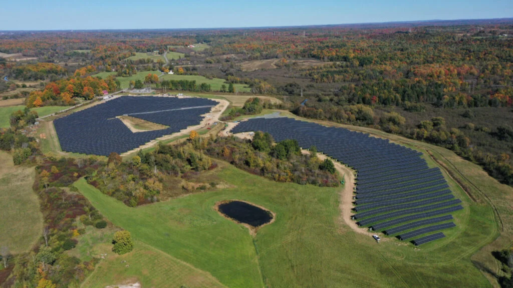
Vegetation management can further improve infiltration capacity. Deep rooted plantings, including pollinator species commonly used on solar sites, improve soil structure and increase the soil’s ability to store water. On many utility scale projects where cropland is replaced with year round vegetation, post construction runoff volumes may decrease compared with pre development conditions.
Where off site inflows from upstream are the primary concern, infiltration alone cannot solve the problem. Improvements within the site boundary cannot control water arriving from outside it.
On one recent project, my team’s modelling revealed that backwater from a downstream culvert could generate up to three feet of flooding across part of the array during a 100-year storm event. Raising the entire racking system would have been prohibitively expensive. Instead, engineers designed a graded swale along the upstream edge of the array to intercept and redirect incoming runoff around the panel field. The solution protected the solar array without requiring changes to the racking system.
Detention ponds remain one of the most common stormwater mitigation measures required by permitting authorities. However, they can introduce operational challenges. In colder climates, standing water beneath tracker rows can freeze after winter rainfall events, create safety hazards and limit access for maintenance personnel. Locating detention infrastructure along the perimeter of a site, rather than beneath the array, can reduce these operational complications.
Sites located near wetlands present additional design constraints. Regulatory buffers may limit the available space for drainage infrastructure, and compensatory storage requirements can influence the final array layout. Early hydrological assessment ensures these constraints are incorporated into the design before they become obstacles during permitting.
| Risk source | Primary mitigation measure(s) | Key constraints | Design consideration |
| On-site runoff from impervious surfaces (roads, hardstand) | Infiltration trenches; vegetated swales; deep-rooted/pollinator plantings | Soil type—most solar sites are Type C or D (low infiltration) | Post-construction runoff must typically not exceed pre construction levels; solar with year-round vegetation often meets this without additional infrastructure |
| Off-site inflows from upstream land | Perimeter graded swales to intercept and redirect upstream runoff around the array | Cannot be solved by on-site infiltration alone; swale must have adequate freeboard capacity | Swale alignment should be determined by H&H modelling, not assumed from topography alone |
| Downstream backwater from degraded or undersized culverts | Compensatory storage; racking elevation adjustment; grading modifications to redirect flow | Culvert condition and capacity data must be sourced from municipal/county records and field-verified | Backwater effects may not be visible in desktop review—requires HEC-RAS modelling with actual culvert inputs |
| Detention requirements (regulator-mandated) | Detention ponds; extended dry detention basins | In cold climates, standing water beneath tracker rows can freeze, creating safety hazards and restricting maintenance access | Locate detention infrastructure at site perimeter rather than beneath the array wherever possible |
| Sites near wetlands | Reduced-footprint drainage solutions; compensatory storage sized to regulatory requirements | Regulatory buffers limit available space; compensatory storage requirements may influence array layout | Wetland constraints must be incorporated into design basis at concept stage—cannot be resolved during permitting |
Regulatory considerations
Regulatory, insurance and financing pressures
Regulatory expectations for flood analysis for solar developments are becoming more rigorous. Authorities Having Jurisdiction (AHJs), including counties, municipalities and state agencies, increasingly request project specific hydraulic modelling results to verify base flood elevations—even where FEMA floodplain maps already exist.
One reason for such requests is that, as previously mentioned, many reference maps are outdated. Requiring site-specific HEC RAS modelling allows regulators to obtain more current data and improve their own floodplain records.
Hydrologic and hydraulic modelling also supports the development of Stormwater Pollution Prevention Plans (SWPPPs), like those required under the US National Pollutant Discharge Elimination System (NPDES) construction stormwater programme. Modelling results help engineers identify drainage pathways, flow concentrations and erosion prone areas that must be addressed through erosion and sediment control measures. Incorporating H&H analysis into SWPPP development enables project teams to design stormwater controls that meet regulatory requirements, while reducing the likelihood of sediment discharge during construction.
Insurance providers and project lenders are also increasing their scrutiny of flood risk. Flood-related losses at solar installations have prompted insurers to request site-specific flood exposure analyses before issuing coverage. Lenders’ financing projects located within or near FEMA Zone AE (high-risk) floodplains increasingly incorporate hydrological analysis into their due diligence requirements.
Submitting permit applications without adequate flood analysis often results in review comments requiring additional modelling. Addressing those requests during the permitting review cycle can extend project timelines by months. These pressures from regulators, insurers, and financiers are gradually pushing hydrological analysis earlier in the development process.
The financial case for early hydrological investment
Engineering decisions made early in the design process are relatively inexpensive to change. Once permitting or construction begins, those same changes become far more costly.
Consider a large utility-scale project with 100,000 structural piles. If flood exposure identified late in design requires increasing pile height by six inches, each pile may require 10 additional pounds of steel. At US$0.70-1.00/lb., the cost of this modification becomes US$700,000-1,000,000 in additional material costs alone.
Similarly, discovering the need for a detention basin during permitting review may require relocating array blocks, modifying equipment layouts and updating interconnection calculations. These revisions introduce additional engineering costs and delays.
In comparison, the cost of conducting comprehensive modelling during early project design is small. Once LiDAR data and baseline models are established, running additional scenarios—such as back to back storm events, saturated soil conditions, or partial culvert blockage—requires minimal additional effort.
These analyses provide developers with something extremely valuable: certainty. Rather than assuming flood exposure risk, they can quantify it and demonstrate their findings to regulators, insurers and lenders.
Beyond construction costs, flood events can generate additional financial impacts, including lost energy production, insurance processing delays, disputes with neighbouring landowners and reputational damage in communities where future projects may be proposed. A modest design intervention, such as a perimeter swale installed early in the design process, can prevent these outcomes at a fraction of the potential cost.
| Issue | Identified at concept stage | Identified after 60% design |
| Racking elevation adjustment (e.g. +6 inches across 100,000 piles) | Minor change to design basis; negligible cost | ~10 lbs additional steel per pile at US$0.70-1.00/lb = US$700,000-1,000,000 in material costs, plus additional labour |
| Detention basin location or sizing | Incorporated into layout; no array displacement | May require relocating array blocks, revising equipment layout and up |
| Off-site upstream inflow | Mitigation (e.g. perimeter swale) designed into grading plan from the outset | Potential racking redesign or significant grading changes; possible regulatory resubmission |
| Base flood elevation shift | Layout adjusted before commitments made; compensatory storage sized correctly | Cascading redesign across civil, structural, and electrical disciplines; months of schedule delay |
| Permitting review comments requiring additional H&H analysis | Analysis already complete; no comment cycle triggered | Additional modelling required during review; typically adds weeks to months to permitting timeline |
Futureproofing for climate change
Whether solar projects should be designed to exceed current regulatory flood standards remains a complex question. Design criteria are based on historical probability distributions, while projecting how rainfall patterns will evolve over a 30 or 35 year project lifespan remains uncertain.
However, modelling can still provide valuable insight by evaluating how sensitive a design is to different scenarios. For example, analysing back to back storm events—where a second storm occurs while soils remain saturated from previous rainfall—often reveals vulnerabilities that single event modelling may miss.
Many extreme rainfall events occur during wet seasons when soil is already saturated. Under those conditions, nearly all precipitation becomes surface runoff, significantly increasing flood depths and extents. Scenario-based modelling enables developers to evaluate these conditions and determine how much risk they are willing to accept.
AI’s emerging role in hydrological design
AI is beginning to influence hydrological modelling workflows, though its use in solar development is still nascent.
AI-assisted tools can accelerate tasks that traditionally require extensive manual effort, including terrain classification, watershed delineation and geospatial data analysis. Machine learning techniques can process large datasets such as LiDAR point clouds, satellite imagery and historical rainfall records, helping engineers identify subtle drainage features and potential areas of ponding or erosion.
One promising application of AI is rapid scenario simulation. AI enhanced modelling environments can evaluate hundreds of hydrologic scenarios—including alternative land use conditions, storm sequences, and infrastructure failure cases—far more quickly than traditional workflows allow. These capabilities allow engineering teams to explore a broader range of potential outcomes and identify vulnerabilities earlier in the design process.
The same datasets that support conventional modelling—including high-resolution LiDAR, updated satellite imagery and infrastructure records—will also power AI-assisted analysis. Drone based topographic surveys capable of achieving vertical accuracy of 1-3cm using RTK or PPK GPS are already improving the terrain datasets used for hydrological modelling.
As AI tools mature, they will likely function as decision support systems that enable engineers to conduct more comprehensive analyses while still relying on professional judgement to interpret results.
Early, accurate hydrology reduces risk
Flood risk management in utility-scale solar development is no longer a niche concern limited to sites located within mapped floodplains. It is becoming a mainstream engineering challenge shaped by intensifying storms, evolving watersheds and increasing scrutiny from regulators, insurers and financiers.
Developers and engineering teams that recognise this shift will integrate hydrological modelling at the concept stage, analyse the full watershed rather than only the project footprint and test their designs against multiple storm scenarios.
The tools required to do this already exist. HEC-RAS and HEC-HMS, combined with high-resolution LiDAR data, updated land use information, culvert analysis tools such as HEC-8, and infrastructure records, can produce reliable flood risk models in on to two weeks.
What the industry ultimately needs is a change in sequencing. Hydrology must become a concept stage discipline rather than a permitting phase afterthought. Because in hydrology, as in most engineering, the least expensive intervention is always the one made before the layout is fixed.
Author
Hossein Ghoveisi, PhD, EIT, is manager of civil engineering at Castillo Engineering, a utility-scale solar-plus-storage EOR firm. His experience includes over 15 years of engineering water resource projects, with specialties in hydrologic and hydraulic modelling, HEC-RAS and ArcGIS for hydrologic engineering, water resources engineering project management and coordination, and sustainability engineering design.