
Potential-induced degradation (PID) of PV modules containing silicon solar cells is an issue with high relevance to the long-term reliability of PV systems [1]. Despite knowledge of methods for mitigation of PID for standard module technologies, there are still new cases of PID arising related to new technologies such as bifacial solar cells or cheaper packaging materials. It was observed that even PV modules designed and specified to be “PID-free” can develop PID under particular outdoor conditions.
Especially humid and hot climates in combination with soiling can lead to a change of the electric properties of the module encapsulation, which results in PID degradation of initially “PID-free” modules, in particular when they exhibit a conventional metal frame and a polymeric back sheet, which is to some extent water permeable. This is attributed to the change of the electric conductivity of the glass surface and of the encapsulating materials [2] causing increased leakage currents on the path from the frame across the glass surface and through the module encapsulation layers and thus change of the electric field in the anti-reflective coating (ARC) of the solar cells. each delivering a voltage of about 35V) are switched in series, leading to voltages to ground up to several hundred volts. Both the module glass and the polymer back sheet are no absolute insulators, therefore tiny leakage currents may flow between the cells in the modules and ground.
Try Premium for just $1
- Full premium access for the first month at only $1
- Converts to an annual rate after 30 days unless cancelled
- Cancel anytime during the trial period
Premium Benefits
- Expert industry analysis and interviews
- Digital access to PV Tech Power journal
- Exclusive event discounts
Or get the full Premium subscription right away
Or continue reading this article for free
The leakage current that flows under high-voltage stress of 1,000 V amounts to typically some 10μA/m2 for solar modules with soda-lime front glass and EVA encapsulation. This can be measured outdoors e.g. using the PIDcheck test device, as shown in the cover image.
PID may occur if the voltage drop across the insulating SiN anti-reflective coating (ARC) layer at the top of the cells VSiN exceeds a certain limit, driven by the leakage current. In this work, PID of the shunting type [1] (also called “PID-s”) is addressed since currently it is the most detrimental type of PID.
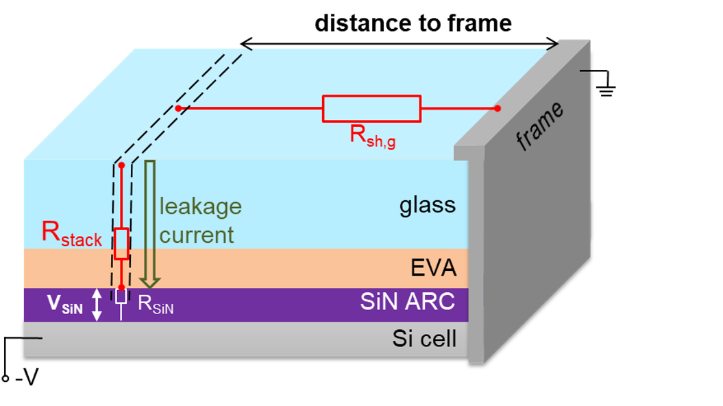
Figure 1 (above) illustrates the leakage current flow in a module. The Si cell is assumed to lie on a high negative voltage -Vc, since only negative cell voltages are known to lead to PID of the shunting type [1], and the metallic frame is assumed to lie on ground potential. Then, for enabling leakage current to flow to the cell at a certain lateral position of the module, first the current must flow horizontally to this position via the glass surface sheet resistance Rsh,g, and then it flows vertically through the stack of glass and the encapsulating polymer ethylene vinyl acetate (EVA) to the cell having a resistance of Rstack. Note that for this stack the EVA layer represents the limiting resistance, since the resistance of the glass is relatively low. On top of the cell there is an anti-reflective coating (ARC) made by amorphous silicon nitride (SiN), which is an excellent insulator.
However, this layer is very thin (below 100 nm) and thus does not contribute significantly to the resistance across the layer stack Rstack. If the voltage across this layer VSiN exceeds 5-10 V, which is well below the cell voltage to ground -Vc, leakage current Jleak flows through, which may lead to PID. It is known that VSiN depends logarithmically on Jleak [3]. Thus, the circuit shown in Figure 1 represents a voltage divider [3], where the leakage current density Jleak and thus the voltage VSiN (being critical for PID) becomes the larger, the lower the sum of Rsh,g and Rstack is. In this work, the specific variations of the resistors Rsh,g and Rstack are to be determined quantitatively in dependence of soiling and the humidity soaking process.
In the approximation of ohmic resistors the voltage across the SiN ARC VSiN along a specific current path or location at the module, respectively, is given by;
VSiN=Vc RSiN ⁄ (Rsh,g+Rstack+RSiN ) Jleak (1)
This is an extract of a technical paper first published in Volume 22 of PV Tech Power. The full technical paper can be read here, or in the full digital copy of PV Tech Power 22, which can be downloaded for free here.


