With global installed capacity increasing from 97MW in 2016 to an expected 5,420MW by the end of 2019 – the promise of bifacial photovoltaic (PV) solar has begun to materialise.
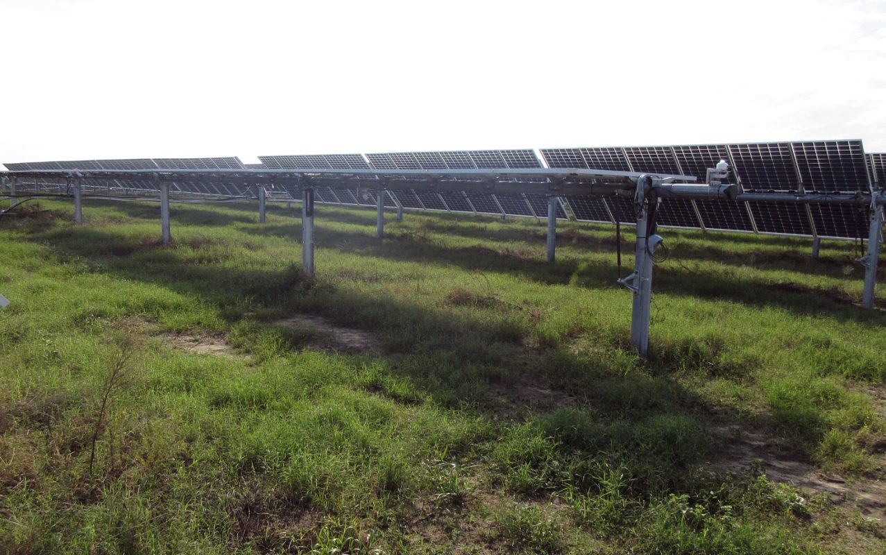
As a leading independent renewable energy company, RES has seen a marked increase in owner/developer procurement of bifacial solar modules over the past two years. RES currently has over 550MW DC of bifacial capacity in the design/engineering phase and recently completed construction of a larger than 200MW utility-scale bifacial project.
Try Premium for just $1
- Full premium access for the first month at only $1
- Converts to an annual rate after 30 days unless cancelled
- Cancel anytime during the trial period
Premium Benefits
- Expert industry analysis and interviews
- Digital access to PV Tech Power journal
- Exclusive event discounts
Or get the full Premium subscription right away
Or continue reading this article for free
Currently, this is one of the largest utility-scale bifacial projects in the USA. Standard industry practices for utility-scale PV design, construction and testing can be impacted by the integration of bifacial technology. This article provides a preliminary look at rear-side irradiance gains and addresses some of the valuable design and construction lessons learned RES has garnered thus far.
Design and construction overview
Lessons learned on bifacial utility scale projects RES has designed or constructed thus far and that are addressed in this article include:
- DC collection system design;
- DC collection system construction;
- Commissioning and testing considerations;
- Meteorological station equipment and locations;
- Measured rearside irradiance observed thus far.
DC collection system design
PV array output current is directly proportional to the amount of irradiance incident on the PV arrays. The instantaneous current value can be impacted by albedo, reflections, cloud edge effect, and site elevation. Bifacial module cells are exposed on both sides and cell exposure to rear-side irradiance should result in increased PV output current as compared with monofacial modules. Therefore, design of the PV DC collection system must consider total incident irradiance when sizing the DC current carrying conductors and fuses. The US National Fire Protection Association (NFPA) National Electric Code (NEC) is the industry standard for sizing DC conductors and fuses. DC conductors and fuses for projects are sized by determining the maximum current of the PV Source Circuits using NEC 2017 Article 690.8(A).
According to Article 690.8(A), the following equation is used to determine the worst case continuous current that a DC cable may carry under load.
Imax=Isc*IF
Where:
Imax: Maximum PV Source Circuit Current
Isc : Short Circuit Current per module or per string of modules in series. The Isc value is taken from the module manufacturer datasheet at Standard Test Conditions (STC).
IF (Irradiance Factor): To account for increased current due to increased incident irradiance, the default irradiance factor is 1.25, which assumes 25% more irradiance than at (STC) where incident irradiance is assumed to be 1,000W/m2. Therefore, if the module Isc at STC is 10 Amps an Irradiance Factor of 1.25 assumes incident irradiance of 1,250W/m2 and an Isc increase of 25% to 12.5Amps. Even monofacial systems must consider an irradiance factor for situations where the modules experience greater than 1,000W/m2.
The default assumption per Article 690.8(A)(1)(1) is an Irradiance Factor of 1.25 or 1,250 W/m2. However, 690.8(A)(1)(2) allows a licensed electrical engineer to use an industry-approved method for deriving an Irradiance Factor that is different than the default value per NEC 690.8(A)(1). The NEC references the SANDIA 2004-3535 Photovoltaic Array Performance Model and the National Renewable Energy Laboratory (NREL) System Advisor Model (SAM) simulation programme as an industry-approved method for calculating the “highest 3-hour current average resulting from the simulated local irradiance on the PV Array accounting for the elevation and orientation. The current value used by this method shall not be less than 70 percent of the value calculated using 690.8(A)(1)(1)”. In RES’ experience, a method acceptable to owners and independent engineers (IEs) is to model 20 or more years of solar resource data using SAM to determine the highest three-hour average irradiance factor over the 20 years.
Example calculations for a utility-scale bifacial project using 690.8(A)(1)(2) are outlined below. For bifacial systems, the highest three-hour average circuit current must account for the additional current a bifacial module will see due to the rear-side irradiance contribution. Using SAM and historical data, the electrical engineer of record (EOR) can determine the Irradiance Factor. While the SAM POA output values include a rear-side irradiance contribution, in RES’ experience some EORs choose to add another factor of safety by using the module manufacturer published Isc datasheet values multiplied by an additional bifacial gain factor (BGF). RES has seen this BGF value vary from 10-15% across projects. Therefore, in this example the maximum photovoltaic source circuit current per 690.A(A)(1)(2) is calculated as follows:
Imax=Isc*BGF*IF
Where:
Imax = 13.225
Isc = 10
BGF = Assumed Bifacial Gain Factor, 1.15
IF = 1.15
When using the method outlined in NEC 690.8(A)(1)(2), a project can end up with a total safety factor greater than the 1.25 value as dictated by 690.8 (A)(1)(1).
To size the DC overcurrent protection devices, NEC 690.9(B) requires “not less than 125% percent of the PV maximum output current calculated in 690.8(A)” .
Ioc=Imax*1.25
Where:
Ioc = Current value for Overcurrent Protection Rating as required by 690.9(B)
Imax = Max current calculated according to 690.8(A)
1.25 = NEC required safety factor per 690.9(B) that states an Overcurrent protection device can only be run at 80% of its continuous rating.
Using this example, the Ioc as calculated per 690.8(A)(1)(2) and 690.9(B) ended up at 16.53 Amps per module or per module string. The BGF value selected for projects can have material and installation cost implications for the DC wiring system. Due to the limitation imposed by the current industry 32A in-line fuse rating, the BGF factor assumption can result in the purchase and installation of up to two times the number of wire harnesses as compared with an equivalent monofacial project.
As Isc values on modules continue to increase with increased module efficiency, the assumptions around the bifacial gain factor are increasingly important. The DC collection system, including procurement and installation of the DC string wire harnesses and DC conductor homeruns (from field installed combiners to inverters), can comprise 7-8.5% of the total balance of system (BOS) cost stack – not including modules or project substation costs. A higher rated DC in-line fuse (~50A) coming to market could allow for more strings per wire harness. While this would have allowed the current design to use the industry standard method of two-string and one-string harnesses per three-string tracker row, the ability to put more strings in parallel per string, even with a higher fuse rating, will still depend on the EOR assumptions around the IF and the BGF.
If the bifacial current increase assumption is too aggressive owners run the risk of systems blowing fuses or compromising conductor insulation over the life of the project. However, conservative BGF and IF factors can add additional unnecessary capital costs to projects. Important consideration needs to be given to the seasonal and clear sky versus diffuse hourly rear-side irradiance gains when determining the total IF and therefore the assumed worst-case current value.
This is an extract of a technical paper first published in Volume 22 of PV Tech Power. The full technical paper can be read here, or in the full digital copy of PV Tech Power 22, which can be downloaded for free here.


