Inverters are critical to PV system operation but are often over-specified due to inadequate data on which materials and designs ensure optimal performance. Sandy Klegel of Fraunhofer IMWS reports on research aiming to develop a more precise methodology for predicting the reliability and lifetime of PV inverters.
Photovoltaic inverters convert the direct current of the connected PV modules into grid-compliant alternating current. In addition to this primary requirement, a steadily growing number of secondary demands have been added in recent years, particularly in grid support functions (provision of reactive power, control power and grid support) and energy management (integration of battery storage, visualisation of load currents, load regulation). The inverter is thus changing from a pure voltage converter to the central component for the energy management of a household or a PV power plant. Nominal outputs from this key component range from a few hundred watts up to the megawatt scale.
Try Premium for just $1
- Full premium access for the first month at only $1
- Converts to an annual rate after 30 days unless cancelled
- Cancel anytime during the trial period
Premium Benefits
- Expert industry analysis and interviews
- Digital access to PV Tech Power journal
- Exclusive event discounts
Or get the full Premium subscription right away
Or continue reading this article for free
The inverter consists of numerous individual components, such as power modules with a ceramic-based design, control electronics with a circuit board-based design, switches and intermediate circuit capacitors. This results in a unique set of requirements for the reliability of PV inverters. First, inverters should have a lifespan of at least 15 to 25 years without significant failures. They must operate effectively across a wide temperature range, typically from -40 degrees Celsius to +60 degrees Celsius. In addition, high protection ratings, such as IP65 or higher, are essential to guard against dust and water ingress. Inverters should also be capable of withstanding short-term overloads and meet electromagnetic compatibility (EMC) standards.
The implementation of diagnostic and monitoring functions for failure detection is crucial for maintaining operational reliability. High efficiency is equally important to minimise energy losses during the conversion process. Finally, adherence to safety standards, such as IEC 62109, is necessary to ensure safe operation of the inverter.
Still, it is largely unknown which construction methods, materials and designs ensure performance over the desired service life. In addition, there is little experience in areas such as photovoltaics or electromobility. As a result, inverters are often produced with safety margins and “oversized”. Manufacturers rely on proven processes and materials without fully understanding the ageing behaviour or risk factors, resulting in additional costs. In our recently completed research project, we were able to expand this empirical knowledge with scientific data. The result is a precise methodology for predicting the reliability and lifetime of PV and battery inverters.
Capacitor stress
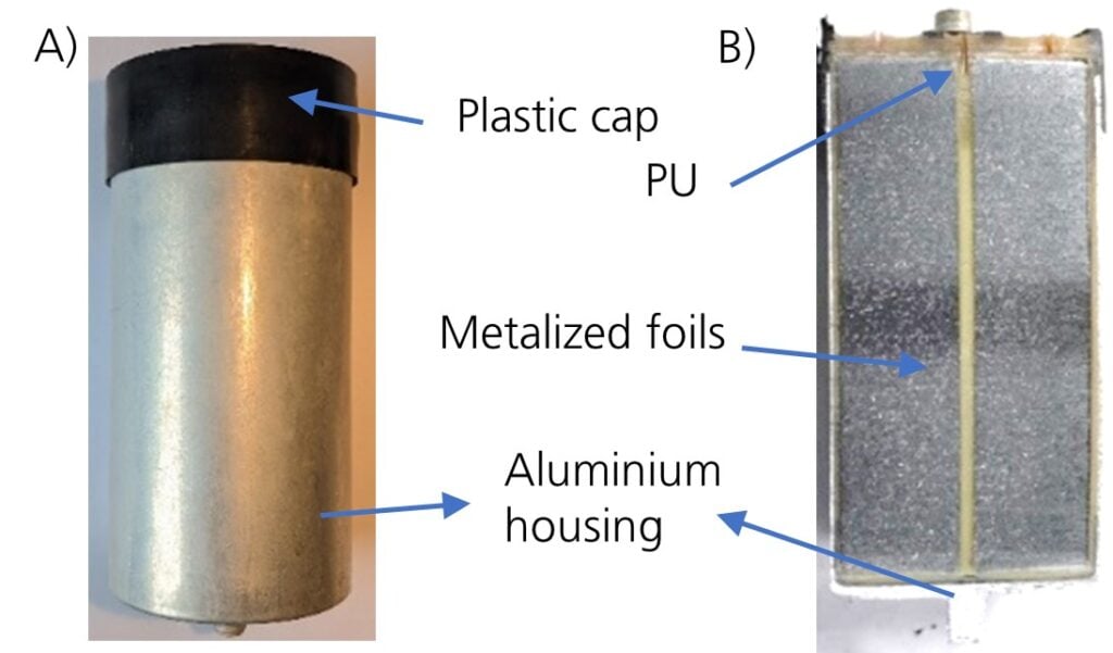
A component subject to heavy stress is the DC film capacitor, where corrosion is often the predominant failure mechanism in accelerated stress tests. Film capacitors are multi-material components, as shown in Figure 1. The housing is comprised of aluminium and protects the capacitor from the effects of ambient conditions. A plastic cap closes the housing. A solid polyurethane (PU) encapsulation encloses and fixes the capacitor coil and protects it from moisture. The coil is made of metallised polypropylene films. The schoopage coating on the top and bottom of the coil serves as the electrical contact to the metallised films (see Figure 1).
For estimating the service life of these capacitors, standardised climate tests with high humidity and high temperatures, and sometimes also with active circuitry, are used in electronics. There is a common assumption that 1,000 hours at T=85°C and F=85% rH correspond to a service life of up to 10 years in normal operation, but in this case, the exact estimation depends to a large extent on the specific capacitor and its properties.
In the course of our research work at the Fraunhofer IMWS, various series of analyses were carried out on aged film capacitors in order to investigate degradation phenomena and failure mechanisms depending on the respective load on the capacitors (voltage, temperature and humidity) and to be able to draw conclusions about their service life. The results obtained were evaluated by comparing them to the analyses of film capacitors in virgin condition and after ageing in use.
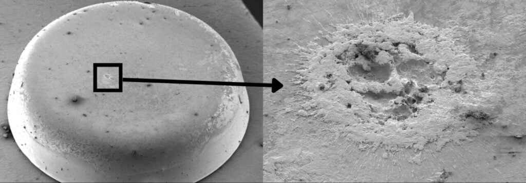
The comparison of the top coating in the initial state (Figure 2), after 875 hours at U=2,200V/ T=90°C/F=70%rH and after seven years of exposure in the field shows massive corrosion of the coating in the sample after stress testing. This corrosion leads to an increase in resistance and locally increased current densities. It contributes significantly to a reduction of the service life of the capacitors. However, the degree of corrosion after accelerated storage in moisture is by no means comparable with field exposure (based on seven years of operation). The degradation effects in the field are much less pronounced.
part after test.

Therefore, a much longer service life can be expected here, unless the accelerated test in combination with electrical voltage, high temperature and high humidity only partially reflects the degradation mechanisms in field use.
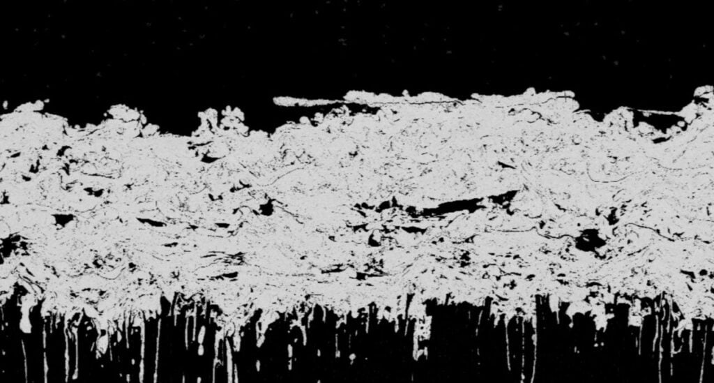
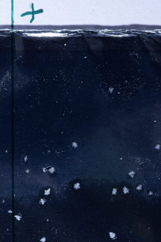
Furthermore, a massive change in the nature of the polyurethane casting can be observed after the accelerated test. The material showed discolouration and was liquefied partially. A holistic consideration of the results of the optical inspection, FTIR- and cross-section analysis shows a correlation between the degradation of the coating due to stress under the selected test conditions and the degradation of the PU.
Figure 3 shows the analyses of the PU through optical inspection and correlating cross-section preparation of the coating. The changes in the coating and the film windings due to the test loads are likely the result of chemical attack from decomposition reactions of the polyurethane. Temperature and humidity stress can cause the polyurethane to hydrolyse. Subsequent chemical reactions can lead to the formation of both amines and carboxylic acids, which increases the acid concentration in the environment and in turn can cause a corrosive attack on the metals.
In summary, the combination of high temperature (over T=60 degrees Celsius) and high relative humidity (over F=60% rH) is critical, as this promotes the hydrolysis of polyurethanes and can lead to their chemical decomposition. The usual test conditions for lifetime predictions (e.g. T=85 degrees Celsius, F=85% rH) lead to over-testing of the components and to non-representative failures, especially in DC capacitors with the design shown above. For well-founded lifetime predictions, the test conditions must be adapted and further correlated with field data.
Moisture ingress
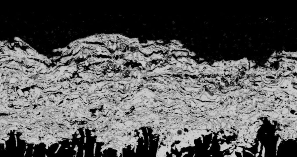
Thermally coupled permeation simulations were carried out to visualise the moisture ingress numerically and to provide a base for simulated lifetime estimation. The analytical results show that the moisture ingress starts from the top of the capacitor in the area of the plastic cap. Therefore, the material characteristics of the polyurethane encapsulation and the foil stack were determined experimentally at T=50 degrees Celsius and T=85 degrees Celsius with F=85% rH in each case and the resulting time-dependent moisture distribution in the capacitor was simulated (Figure 4).
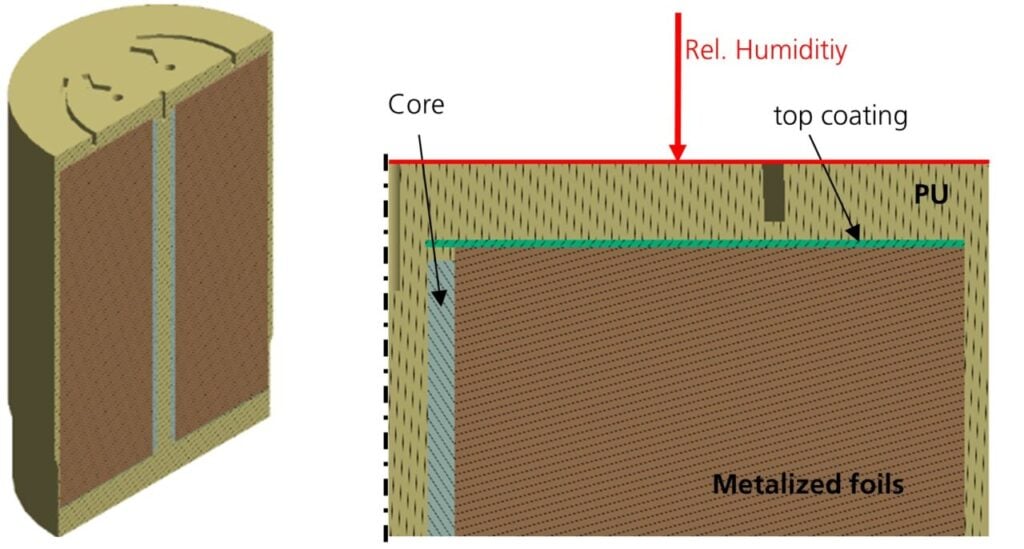
The results after t=~500 hours initially show a distribution of moisture in the PU above the metallisation. After t=~5,000 hours, the distribution of moisture in the PU has progressed, with the higher diffusion coefficient at T=85 degrees Celsius becoming apparent by the deeper penetration. After ~10,000 hours, the moisture has also diffused into the films. The higher diffusion coefficient of the films at T=85 degrees Celsius is also reflected in the simulation results.
In summary, it can be concluded that the accelerated tests for predicting the service life of DC film capacitors need to be adapted depending on the design. Testing at high temperatures and humidity levels leads to failure mechanisms that do not occur at all or only very slowly in actual field components. Therefore, we can assume that the service life in the field is significantly longer in some cases.
Silicone gel testing
In addition to the film capacitors themselves, the power modules used are also exposed to heavy loads and day-night cycles with corresponding moisture exposure. Power modules are typically encapsulated with a silicone gel to protect the modules from direct exposure to moisture and contaminants. Silicone gels used in these applications typically have low moisture absorption and high purity. Thermomechanical stresses that can occur at the interface of electronic components such as DCB substrates or power semiconductors are low due to the softness of the silicone gel.
While the low glass transition temperature and high polymer chain mobility provide the desired softness across a high temperature range, they also enable high mobility of the molecules throughout the polymer network compared to other, more rigid encapsulation materials. While the water absorption of the gel is low, the permeation rate is high, and thus, water molecules can reach the surface of the encapsulated materials. Under unfavourable conditions, water films can form, which are a prerequisite for several corrosion processes.
A multitude of contaminants, which are not necessarily corrosive in themselves, can then accelerate corrosion under humid conditions. In addition, electrochemical migration (or ion migration) can take place under these conditions. This usually occurs at temperatures below T = 100 degrees Celsius in the presence of moisture. Silver, copper and tin – typical metallisation materials in electronics – tend to be susceptible to migration. The passivation layers of these metals are relatively weak, and only a low potential is required for an attack, correlating to the electrochemical activation energy.
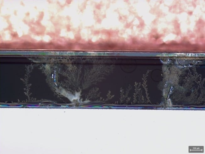
Metals on the conductor with higher potential are oxidised to a soluble state, resulting in positively charged metal ions. These ions move in the electric field via moisture paths towards the negatively charged contact, where they are reduced again. A higher current density at the tips of the formed core structure leads to an increase in further deposition. This creates a characteristic dendrite with a defined crystallographic structure.
In the literature, it is often assumed that the surface insulation resistance decreases throughout the process of electrochemical migration. Failure occurs when metal ions accumulate to a critical concentration. This can occur even without the formation of dendrites by the surface insulation resistance deteriorating by several orders of magnitude in a short time.
Impurities such as halides and sulphur can accelerate the electrochemical migration reaction. Even changes in pH near the metals involved can accelerate the effect by destroying protective oxide layers. Several studies have shown the influence of pH and halide contamination on corrosion processes of e.g. copper wire connections and their intermetallic layers.
There is an assumption that the protective oxide of the metals is weakened by the chemical influences (a lot of metal oxides are dissolved at low pH values <7 and sometimes at high pH values > 10, e.g. Al2O3). Once passivity is reduced, pitting corrosion can occur, and electrochemical processes are accelerated. In power electronics, these mechanisms are mapped out via the “Highly Accelerated Life Test for Reliability Benchmarking” (H3TRB test).
This test simulates extreme operating conditions to evaluate the influence of temperature and humidity on the reliability of materials and components. The results of H3TRB can be used to estimate the expected lifetime under normal operating conditions. For example, if a component survives 1,000 hours under H3TRB conditions, it can be assumed that it can function reliably for thousands of hours under normal conditions.
A comparative assessment was conducted to gain a deeper understanding of the accumulation and migration of contaminants, as well as their enrichment in the silicone gel power modules of photovoltaic string inverters after approximately eight years of operation and following a condensation test. To determine the accumulation of contaminants, silicone gel samples were taken from three locations in each power module.
The silicone gel samples were analysed for a wide range of elements using ICP-MS. For evaluation and discussion, only those elements present in at least one sample with more than 1,000 ng/g (1 ppm) were considered.
Potassium and platinum were detected in consistent quantities in all samples. Platinum is used as a cross linking catalyst and can therefore be a component of the silicone gel; the same applies to potassium. Phosphorus and chlorine were also detected in amounts of 2 and 6 ppm in the reference module.
Compared to the reference modules, a significant increase in certain elements in the silicone gel could be observed in the field modules. The greatest accumulation was found for phosphorus and chlorine.
Chlorine levels varied between the field modules of different installation sites, while it was homogeneously distributed in the modules of the same inverter. The field modules of site A showed the highest accumulation, while the field modules from site C had similar chloride levels to the reference module. This indicates that site-specific conditions or events may have influenced the extent of chlorine accumulation.
Phosphorus levels were the same for all field modules, with a homogeneous distribution within the modules. This indicates phosphorus accumulation originating from a source present in all the tested inverters and not significantly affected by external conditions or specific events.
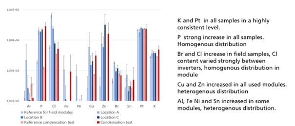
A moderate increase in bromine was found in a homogeneous distribution within the field modules. In some modules, increased quantities of other elements, such as aluminium, copper or zinc were detected. The quantity of these elements even varied by several orders of magnitude between silicone gel samples taken from the same module, indicating a highly localised element accumulation. In the quick-tested modules, phosphorus increased in a similar quantity compared to the field modules and showed a uniform distribution within the modules. Elevated copper and zinc levels were detected because the levels fluctuated greatly even within the same module of the field modules. The halides chlorine and bromine showed no significant increase in the dew test.
Various analyses were carried out to show possible sources of the elements detectable in the gel. By examining the chemical composition of the module components, potential sources were identified for most of the elements concentrated in the silicone gel of the field and test modules, in the electronic components, in the module housing or in the materials used for assembly (see Figure 8). A notable exception is chlorine, which can be classified as an external contaminant that reduces reliability, based on the analyses.

The increased halide levels can cause the corrosion resistance of the inverters to decrease over time. The long-term condensation test therefore does not fully reflect the stresses to which the modules are exposed due to the local environmental conditions. Further research and test developments are needed here, to cover the influence of day/night cycles and external contamination as well.
Author
Sandy Klengel is group leader at the Fraunhofer Institute for Microstructure of Materials and Systems (IMWS), specialising in the assessment of electronic systems. With more than 20 years of professional experience, she has developed extensive expertise in microstructural based reliability assessment of micro- and power-electronic components.
Acknowledgement
The analysis of the capacitors was carried out as part of the project “Reliability Design” funded by the Federal Ministry for Economic Affairs and Energy (project number 03EE1054C). The analysis of the polymer housing was carried out as part of “iRel40”, an innovation project co- nanced by the EU and funded by the ECSEL Joint Undertaking (JU) under grant number 876659. The silicone gel analysis was carried out as part of “power4re”, supported by the Fraunhofer internal programmes under grant number PREPARE 840225.


