The inverter helps prevent fires in solar systems but can also cause them if not properly specified. Clean Energy Associates’ Ankil Sanghvi looks at the details of inverter architecture that should be investigated to prevent the worst from happening.
Unlock unlimited access for 12 whole months of distinctive global analysis
Photovoltaics International is now included.
- Regular insight and analysis of the industry’s biggest developments
- In-depth interviews with the industry’s leading figures
- Unlimited digital access to the PV Tech Power journal catalogue
- Unlimited digital access to the Photovoltaics International journal catalogue
- Access to more than 1,000 technical papers
- Discounts on Solar Media’s portfolio of events, in-person and virtual
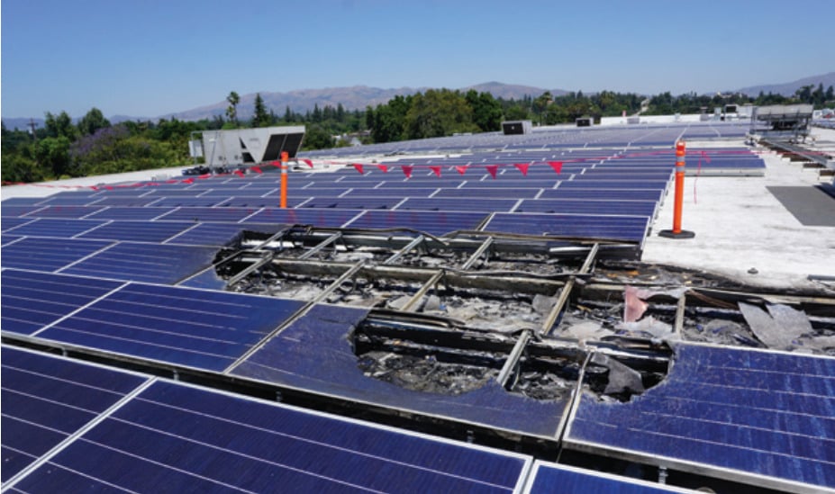
When a fire breaks out at a solar power plant, the consequences can be devastating—not just for the facility but also for the surrounding environment and local communities. Recent high-profile incidents underscore the urgent need to understand and mitigate these risks.
Thermal events, including fires, have not only led to significant financial losses and operational downtime but have also raised serious questions about the safety and reliability of solar energy infrastructure in general. Understanding the root causes of such fires is crucial for preventing future tragedies and ensuring the continued growth of renewable energy.
While many of these fires can be traced back to poor installation practices, Clean Energy Associates (CEA) has found deeper issues at play in our deep dives on behalf of customers in the wake of thermal events. The four main pillars of PV system construction are planning/design, equipment selection, constructability and serviceability.
Most of the failures CEA has come across could have been avoided by appropriate due diligence from a third party. In this article, we will discuss some of the lesser-known problems we have found, which could only be uncovered by thorough analysis of the faulty components.
With the increasing push towards more compact and efficient inverters, the risk of thermal management issues and design flaws has become a heightened concern. Inverters, the heart of photovoltaic (PV) systems, are vital for converting direct current (DC) power from solar modules into usable alternating current (AC).
Understanding the issues that may occur with the inverter and selecting the right equipment is essential for advancing the efficiency and safety of solar PV systems. Proper thermal management, adherence to industry standards and meticulous attention to design details can prevent the severe consequences of electrical faults and thermal runaway.
Insulated gate bipolar transistor systems
In one recent case, the problem started within the inverter. The Insulated gate bipolar transistor (IGBT) is the main switching element in an inverter, converting the direct current into alternating current. IGBTs switch the incoming direct current from the solar array to create pulses with varying widths through a process called pulse-width modulation. This process involves rapidly turning the IGBTs on and off, creating a series of pulses that alternate between positive and negative values. These pulses are then passed through filters such as inductor-capacitor filters to smooth them into a continuous sine wave, resulting in alternating current.
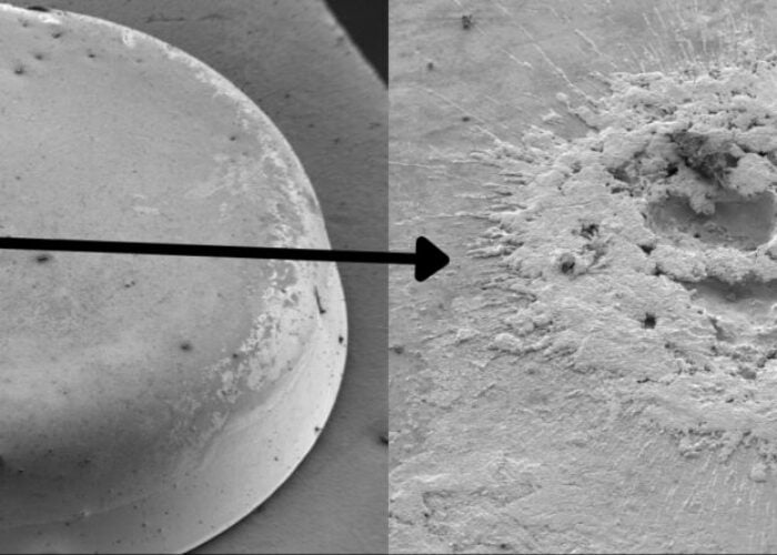
Problems with thermal management can start with the IGBT architecture. It is crucial to select the right inverter for the PV system, by consulting with a third-party expert at the project design stage. In one instance on a client’s site, after our investigation of a thermal event, CEA found issues involving inappropriate separation between IGBT components, not adhering to proper clearances and creepage distances on the circuit boards. Inadequate separations can lead to electrical arcing inside the inverter, potentially causing thermal runaway, an uncontrolled chain reaction caused when heat is unable to dissipate. This thermal runaway can result in overheating and, in severe cases, fires.
Clearance and creepage distances
Clearance and creepage refer to the distances between conductive parts, such as traces on a circuit board or electrical terminals. Clearance is the shortest direct path through the air between two conductive points, from point A to point B. Conversely, creepage is the shortest path along the surface of an insulating material between two conductive parts.
To increase the creepage distance, the path may be routed to follow a recessed channel on a circuit board, tracing down one side, across the bottom, and up the other side. There are specific codes and standards that dictate the required distances for clearance and creepage to ensure safety and prevent electrical arcing. These clearance and creepage distances for inverters are governed by Underwriters Laboratories standards, such as UL 1741 and UL 840. National Electric Code article 690 governs photovoltaic systems and requires adherence to UL 1741 and UL 840.

The required clearance and creepage distances are influenced by factors such as voltage, pollution degree and environmental conditions. High potential (HIPOT) tests are used in the quality assurance process to confirm that high voltage does not cause an electrical breakdown between two points. HIPOT testing helps ensure the insulation integrity of components by applying a high voltage and checking for any insulation failure or arcing. This test verifies the breakdown voltage capability of the insulation. Moisture and contaminants can influence the breakdown voltage.
In root cause analyses that CEA supported, issues with internal architecture became evident in certain cases. Design changes were made without conducting the necessary HIPOT testing.
As manufacturers are pushed towards creating smaller inverter footprints, the clearance and creepage distances have sometimes become more aggressive. This has led to a condensed internal layout, with components positioned very close to each other within the inverter, increasing the risk of arcing and electrical breakdown at terminals and along circuit paths on printed circuit boards. A third-party expert can help in making the right selection of equipment while the project is still in its design phase.
Pollution degree ratings
The pollution degree for the equipment housing describes the level of contamination by conductive or non-conductive materials that impact electrical insulation performance and safety. It is categorised into four levels, ranging from no pollution (Degree 1) to continuous conductive pollution (Degree 4). This classification is required to determine the required clearance and creepage distances, with higher pollution degrees necessitating greater distances to prevent arcing and electrical breakdown. Equipment manufacturers must ensure robust insulation for inverters and perform stringent testing to guarantee safe operation under specific conditions.
Inverter manufacturers may aim for a pollution degree 2, which allows them to reduce the size of the inverter cabinet. If it is a large inverter cabinet such as a central inverter, it may have a pollution degree of 3 or 4, which would have a less stringent capability of keeping out moisture and debris compared to cabinets of smaller inverters. The distances between each component will be greater and, consequently, the cabinets will be bigger.
The shift towards higher output in smaller footprints can drive the inverter designer to reduce the distance between multiple components in the IGBT. This can inadvertently lead to a misapplication of the standard, potentially leading to performance and safety issues.
Case study: root cause analysis
CEA was recently engaged to perform a root-cause analysis of thermal events at several sites on behalf of the PV system host. At multiple locations, inverters had failed similarly, with thermal events originating in the same location within an inverter. A comprehensive analysis of these failed units was completed off-site to determine the root cause of the thermal event. Each unit was diligently examined to identify the origin point of the fault and the cause of the thermal event.
CEA identified a common mode of failure with the units examined. These failures occurred within the factory-sealed power head of the inverter. This mode of failure ended with a thermal event that originated from the inside of the inverter and migrated towards the DC source (the array). This failure could have been initiated due to water ingress, conductive dust from component failure or workmanship issues such as inadequate conductor torque.
Based on the findings from the disassembly of the inverter, the analysis of the resulting damage and the location of the fault, CEA determined that the area in question can be particularly sensitive to any pollution degree or manufacturing inadequacies. Within the inverter, the DC inputs from the wiring box are combined and routed into the power head, attaching the bussing input to the inverter. This bussing appeared to be abnormally close together with a lack of proper insulation.
Conclusion
Prioritising safety and quality in every aspect of solar equipment selection, design and installation is imperative for a PV system’s reliability and performance. Adhering to applicable industry standards is crucial for maintaining the safety and integrity of your installations while also safeguarding against the myriad risks associated with poor design and inadequate testing.
While the trend towards smaller, more efficient inverters is beneficial, safety must not be compromised. Pollution degree ratings should be carefully considered to ensure inverters can withstand environmental challenges without failure. Proper handling, storage and precise installation techniques per manufacturer’s guidelines are vital for preventing electrical issues that could jeopardise the entire system.
Other critical issues that have come up in the past few years include issues with rapid shutdown devices and kitting of equipment. CEA has supported multiple investigations of failures potentially happening as a result of violating manufacturer’s guidelines for installation of Rapid Shutdown Systems that could have been avoided with careful assessment and inspection at the time of design and construction of the system.
Due diligence in equipment selection is another critical factor. Manufacturers selling third-party equipment as part of bundles often lack sufficient due diligence. CEA found multiple fires in 2023 that had been potentially caused by third-party equipment bundled and sold by the inverter manufacturer. Solar developers must avoid the pitfalls of integrating third-party components without thorough vetting, as these can lead to critical system failures.
Ultimately, the foundation of a successful solar installation lies in a holistic approach that encompasses careful design, strict adherence to safety standards, high-quality workmanship and diligent equipment selection. By embracing these principles, solar developers can ensure the creation of efficient, safe and reliable solar power systems that stand the test of time.
Author
Ankil Sanghvi is a senior engineering manager at CEA. He is responsible for inspection and testing services, commissioning services, design reviews and test data analysis. Ankil’s team has completed 700 safety inspections on commercial rooftops, ground mounts, carports and utility systems across 13 countries. He has personally supported over 16 fire investigations as a PV expert onsite.

