Standard mechanical load tests do not account for the effects of wind pressure on PV modules mounted on trackers. Arthur Cao outlines how fresh approaches are needed to ensure tracker-based PV systems are designed adequately to avoid unnecessary failures.
The International Electrotechnical Commission (IEC) 61215 standard series is the foundation for PV module qualification, defining how manufacturers demonstrate durability under mechanical, thermal, and environmental stresses. First introduced in the early 1990s to establish a consistent qualification process for crystalline-silicon PV modules, the series expanded over time to include dynamic mechanical load testing, potential-induced degradation, and bifacial module provisions. However, its mechanical load-test methods were first developed when fixed-tilt structures dominated the market. The industry has since shifted. Single-axis trackers now account for more than 90% of new U.S. utility-scale PV installations [1] with load paths that differ significantly from those of fixed-tilt systems.
Try Premium for just $1
- Full premium access for the first month at only $1
- Converts to an annual rate after 30 days unless cancelled
- Cancel anytime during the trial period
Premium Benefits
- Expert industry analysis and interviews
- Digital access to PV Tech Power journal
- Exclusive event discounts
Or get the full Premium subscription right away
Or continue reading this article for free
IEC 61215-2 specifies two mechanical load tests used in design qualifications:
- MQT 16 – Static Mechanical Load Test: Applies a uniform test pressure of 2,400 Pa on each side of the module for one hour to simulate snow or wind loads. Repeat for 3 cycles.
- MQT 20 – Cyclic (Dynamic) Mechanical Load Test: Subjects the module to 1,000 cycles of ±1,000 Pa oscillating pressure to evaluate fatigue resistance.
Both tests assume a module under uniform, symmetric loading. These assumptions work for fixed-tilt systems but are a poor proxy for capturing realistic demands on modules with tracker-mounted boundary conditions. The generally tighter spacing between module supports in a tracker system produces a longer cantilever at the module free ends, making the response much more sensitive to the uneven distribution of wind pressure.
Industry discussions around this gap are not new. GameChange Solar and CPP Wind Engineering were among the first to highlight the disconnect between standardised mechanical load testing and the dynamic, non-uniform loads experienced on trackers during their 2021 [2] and 2024 [3] technical webinars. In addition, recent upticks in field incidents of glass fracture and frame deformation in otherwise IEC-compliant modules further corroborate that standard testing may not capture the full mechanical spectrum of tracker operation [4]. Such failures underline the need to revisit the underpinning assumptions.
Building on the industry’s earlier recognition of this issue, this article quantifies the mismatch using wind tunnel data and structural analysis, providing a comparative view of how tracker-specific loading diverges from IEC test assumptions. The intent is to provide evidence and practical context that can guide interim design checks and inform the next evolution of the standard.
Trackers under pressure
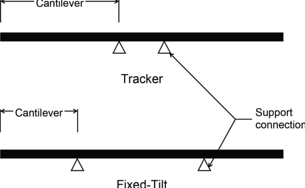
Single-axis trackers impose boundary conditions that differ fundamentally from those of fixed-tilt systems. Most modern trackers use a torque tube to support modules at their midspans, with arms or clips connecting the tube to the module at a single point on each side. Because these attachment points are relatively close together (typically 400-450mm) the module edges extend as long cantilevers—often about 40% of the module length on either side.
In contrast, fixed-tilt systems do not rotate about a central axis, allowing supports to be positioned more efficiently for structural economy. Taking a single-portrait configuration as an apples-to-apples comparison, racking manufacturers often locate supports near the quarter points of the module span, producing a boundary condition of one-quarter-length cantilevers at each end and a half-span simply supported region in the middle. Figure 1 illustrates this comparison, highlighting the much longer free edges in tracker configurations.
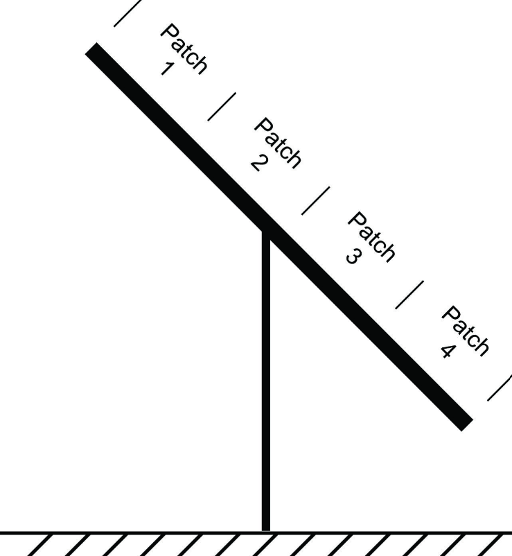
The difference in support geometry is further amplified by the aerodynamic environment. Wind-tunnel data show that pressure distributions across all PV arrays are highly non-uniform. Rather than a single average pressure applied across the module, wind tunnel data we analysed resolve at least four distinct “pressure patches” along its length (Figure 2). At steep stow angles between 60° and 75°—typical for hail protection and wind-stow conditions—pressures can differ sharply between patches, and even reverse sign across the torque tube. In other words, downforce may occur in the leeward patches while uplift acts on the windward side. These asymmetries are a minor issue for fixed-tilt systems but generate far greater bending moments and shear reactions in trackers than those produced under the uniform loading assumed in laboratory tests.
What the data reveal
To examine how standard and real-world loading differ, we analysed a representative tracker configuration for a fictitious US project with moderate design wind speed. The assumed parameters are typical for such sites:
- Risk category: I
- Design wind speed: 110 mph
- Module length: 2.28m
- Ground Coverage Ratio (GCR): 0.287
- Pile spacing: 9m
- Wind exposure: perimeter, end post tributary area
- Tilt: 60 degrees
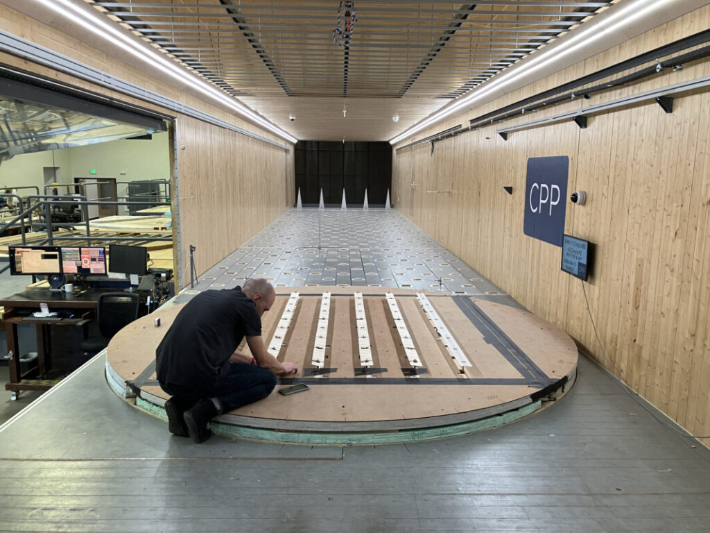
Wind pressures are derived from wind tunnel testing data commissioned by Sol Components and produced by CPP Wind Engineering in Colorado. Pressure coefficients were measured on representative tracker geometries across all possible wind azimuths. Forell | Elsesser Engineers then developed finite-element models to convert those pressure fields into module-level reactions. Two load cases were compared:
- IEC 61215-2 static load (MQT 16) – uniform pressure applied to the entire panel surface.
- Wind-tunnel load cases – non-uniform pressure patches representing realistic tracker aerodynamics.
For simplicity, self-weight was omitted, as it has negligible influence on relative internal forces. The initial comparison assumed a 400mm support spacing typical of modern tracker clamps.
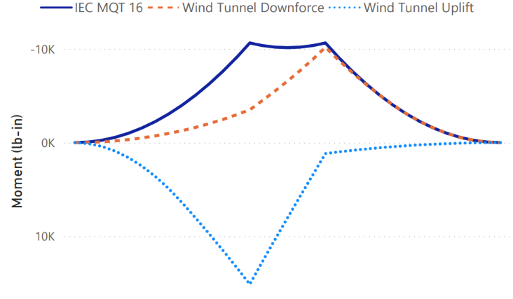
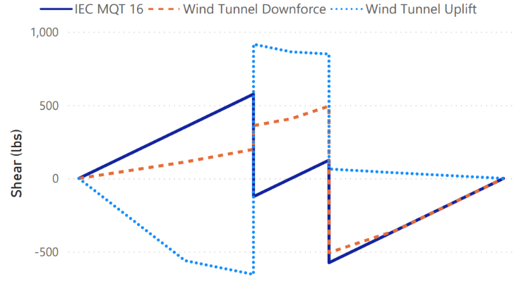
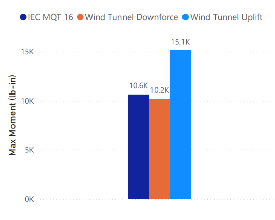
As shown in Figures 3 through 6, the moment and shear demands from wind-tunnel loading exceed IEC predictions by a wide margin. The uplift case is the most severe, producing an absolute maximum moment 42% higher and an absolute shear 59% higher than those from the IEC uniform-pressure tests. Downforce cases generally align with or fall below IEC predictions, except in shear between supports, where localised load transfer produces slightly higher values than the uniform-pressure case.

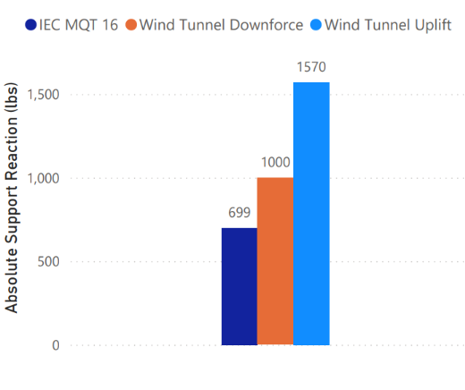
A similar pattern is observed in the support reaction comparison, where both the wind tunnel downforce and uplift cases exceed IEC predictions by 43% and 124%, respectively, as shown in Figure 7.
While the case with 400mm spacing is highly important because that’s the most common tracker panel support spacing for a long time, we also studied how things trend with varying spacing between supports. Note that the module length is held constant at 2.28m. Results are shown in Figures 8 and 9.
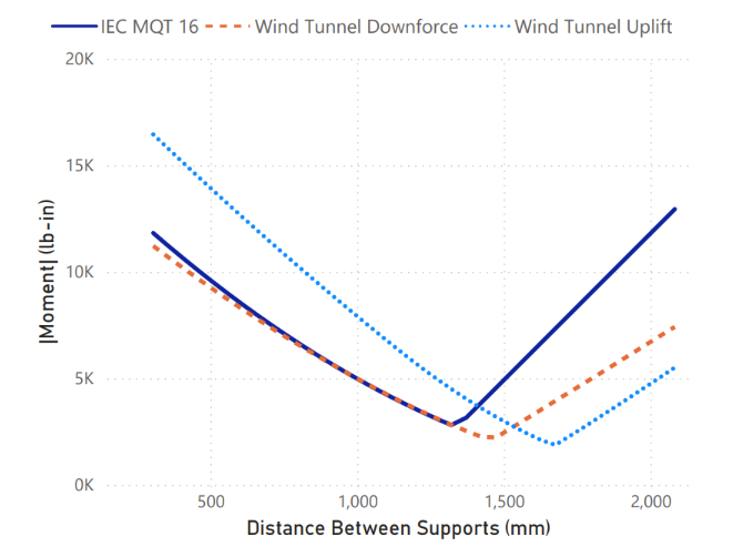
In Figure 8, the wind-tunnel downforce case aligns closely with the IEC prediction up to roughly 1,300mm support spacing, while the uplift case remains about 50% higher than IEC values through approximately 1,400mm. Beyond this point, IEC-predicted moments exceed those from the wind-tunnel cases. Similarly, for shear, shown in Figure 9, the wind-tunnel uplift condition governs up to 1,400mm, beyond which the IEC curve becomes dominant. Particularly notable is the sharp increase in uplift shear demand below 500mm spacing—a far steeper rate of change than that observed for bending moments.
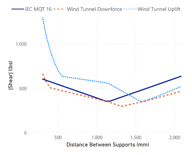
These results confirm that IEC 61215-2 substantially underpredicts mechanical demands for tracker mounted modules under realistic wind excitation. While greater support spacing (>1,400mm) can cause the IEC test to overpredict, such configurations are rare in current tracker designs and are unlikely to be pursued due to constructability and cost constraints.
From compliance to performance
The data suggest that modules that pass IEC mechanical tests often perform reliably on fixed-tilt systems but may experience premature failures when installed on trackers. The problem is compounded when modules qualified under fixed-tilt boundary conditions are later deployed on trackers without retesting. Although the IEC standard requires testing that reflects actual mounting conditions, modules are sometimes assumed to be fully compliant simply because they have been “already tested per IEC 61215”. In tracker applications, this can lead to situations where the racking remains structurally sound while modules suffer cracked glass, delamination, or cell damage.
The issue extends to coordination between design disciplines. Tracker systems are typically optimised for minimal material use, often reducing the distance between module supports to cut costs. Module manufacturers, by contrast, may qualify products using the support geometry assumptions that are more advantageous to the module’s performance—conditions that can degrade significantly if spacing is reduced. When these conflicting assumptions meet in the field, both parties may believe they have met their obligations, yet overall system reliability suffers.
The same misalignment also complicates hail-stow strategies. Increasing stow angles improves hail resilience but amplifies wind-pressure variability across the module, especially for interior tracker tables where partial aerodynamic sheltering is assumed.
Responsibility for addressing this gap is diffuse. Module manufacturers can legitimately claim compliance with the current IEC framework, while tracker OEMs face market pressure to reduce system costs and have limited influence over module selection. Developers and structural engineers are often left to reconcile these boundary-condition mismatches without formal industry guidance, resulting in fragmented accountability across the project team.
Ultimately, this disconnect raises long-term O&M costs and warranty exposure for all stakeholders. The most effective remedy lies in prevention—through early coordination among module suppliers, tracker designers and engineers before products are qualified for deployment.
Bridging the gap
Improving alignment between module qualification and tracker design depends on collaboration rather than blame. The most reliable projects engage all parties early in the design process, when assumptions about boundary conditions and loading can be compared and reconciled.
A practical workflow begins with information exchange. The module manufacturer should document the boundary conditions and load applications used during IEC testing. The tracker OEM should provide details of module-support geometry, operational tilt envelope and stow strategies. The structural engineer of record or an independent engineer can then evaluate equivalence and identify any adjustments required. Where conditions differ, the parties can jointly determine whether to increase support spacing or perform supplemental testing to validate performance.
Three checks before relying solely on IEC qualification:
- Confirm that tracker support spacing matches the IEC test boundary conditions.
- Review wind-tunnel or CFD data to evaluate the impact of non-uniform pressure.
- Plan additional testing or analysis when deviations are identified.
Toward a better standard
IEC 61215-2 has served the industry well, but its next evolution must better capture tracker-specific conditions. A pragmatic first step would be to require formal documentation of the boundary conditions used in mechanical load testing, accompanied by a statement of equivalence to in-field mounting.
Beyond documentation, the development of a new Technical Report could establish procedures for applying non-uniform pressure fields derived from wind-tunnel or computational studies—an incremental extension similar to how cyclic mechanical load testing (MQT 20) was introduced in the 2021 revision.
Progress will rely on consensus. Module manufacturers, tracker OEMs, structural engineers and wind-engineering specialists each possess a piece of the puzzle. A tracker-specific annexe or working group under IEC TC82 would help ensure that design qualification remains relevant as module formats, mounting geometries and site exposures continue to diversify.
Conclusion
IEC 61215-2 remains the backbone of PV module reliability, yet it no longer fully reflects the mechanical realities of tracker-mounted systems. The tools to close this gap already exist—wind-tunnel data, finite element analysis and coordinated design practices. By integrating realistic boundary conditions into qualification testing, the industry can enhance confidence in long-term performance while preserving the integrity of the standard that has long defined solar reliability worldwide.
References
[1] Bolinger, M. and Seel, J. 2023, “Utility-scale PV in the US is poised for liftoff”, PV Tech Power, Vol. 37, pp. 40–44.
[2] Van Pelt, S., Chang, D., and Fewless, Y. 2021, “Module wind load resistance: Standards vs. reality”, PV Magazine Webinar
[3] Van Pelt, S. and Fewless, Y. 2024 “Choose the right direction: Designing for wind directionality and extreme weather for solar assets”, PV Magazine Webinar
[4] Weber, T., Boruha, M., Agada, R., Pyles, J., Lu, M., & Xuereb, S. 2023. “Glass breakage-a growing phenomenon in large-scale PV”, PV Magazine Webinar
Author
Arthur Cao, SE, is a senior engineer at Forell | Elsesser Engineers in San Francisco. He has worked on a wide range of renewable energy projects in both seismically active and hurricane-prone regions. A licensed Structural Engineer in the State of California, Arthur holds a B.S. in civil and environmental engineering from Rice University and an M.S. in structural engineering from Stanford University.


