
Traditional PV inspection methods using direct current polarisation have proved unreliable in detecting certain issues. Researchers from Enertis Applus+ detail a new approach to defect detection aimed at improving the efficiency of PV system maintenance and performance analysis.
The solar photovoltaic (PV) industry is experiencing rapid growth worldwide, driven by its competitiveness and the global push for clean energy sources. According to the International Renewable Energy Agency (IRENA), solar power reached a global capacity of over 1.4TW by the end of 2023, making it the largest renewable power source. This expansion underscores the need for reliable and efficient PV systems to meet increasing energy demands and ensure the expected performance and return on investment.
Try Premium for just $1
- Full premium access for the first month at only $1
- Converts to an annual rate after 30 days unless cancelled
- Cancel anytime during the trial period
Premium Benefits
- Expert industry analysis and interviews
- Digital access to PV Tech Power journal
- Exclusive event discounts
Or get the full Premium subscription right away
Or continue reading this article for free
In this context, early and accurate defect detection within PV modules is critical, as undetected failures can compromise the energy output and long-term profitability of solar installations. Traditional inspection methods, such as electroluminescence (EL) imaging using direct current (DC) polarisation, have served as the industry standard for years. While effective in identifying visible anomalies, such as cracks or disconnections, these methods often fail to detect latent issues, such as potential-induced degradation (PID) or poor soldering joints.
To overcome the limits of conventional testing approaches, Enertis Applus+ has developed innovative solutions to increase defect detection accuracy and improve the efficiency of PV system maintenance and performance analysis, with the ultimate goal of mitigating project risks. These advancements include AI-based tools for efficient analysis of data from PV assets and enhanced inspection methods that integrate drones and aerial vehicles for capturing EL images, among others.
Limitations of conventional DC methods
DC-based EL imaging has long been the standard technique for detecting visible defects in PV modules, such as cracks, disconnected areas and poor soldering. However, despite its widespread use, this method has several notable limitations that can lead to undetected module performance deterioration over time. These limitations are primarily associated with the application of DC current and its ability to detect certain types of defects under specific conditions.
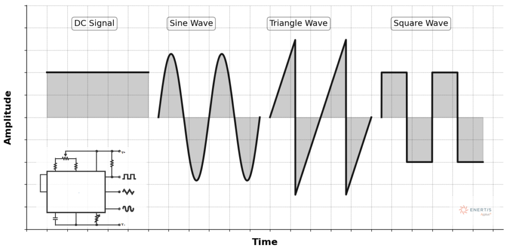
Is there potential for further development in the field of EL imaging, particularly in terms of its applications and services for the photovoltaic industry? This is an important question for the future of PV diagnostics. To explore this further, we turn our attention to the use of different types of waveforms in EL imaging. In Figure 2, a comparison between the traditional DC waveform and non-DC ones, such as sinusoidal, triangular and square waves is presented. These variations in waveforms can potentially offer more comprehensive defect detection, improving the versatility and effectiveness of EL imaging as the technology evolves.
The main limitations of DC current methods include:
Incompatible defects. One of the main challenges associated with DC-based EL imaging is that it cannot effectively identify all types of defects, as certain issues require specific types of current to be detected. For instance, defects such as cracks, poor soldering and damage to the module’s finger contacts generally require the application of high DC currents to become visible. In contrast, low DC currents are needed to detect potential-induced degradation (PID) and light- and temperature-induced degradation (LeTID), which are more subtle but potentially more damaging. As a result, these two categories of defects cannot be simultaneously detected using traditional DC methods since, when DC current is applied, the intensity is either too high to reveal PID and LeTID degradation or too low to properly highlight mechanical defects such as cracks.
This limitation compromises the overall reliability of EL imaging and may lead to critical defects being overlooked. Moreover, the inability to detect PID and LeTID can have a significant longterm impact on module performance, particularly in regions where environmental factors, such as high humidity or temperature fluctuations, are conducive to such degradation.
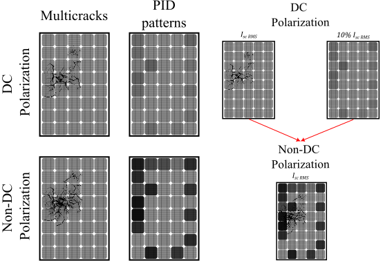
Figure 3 illustrates how non-DC polarisation electroluminescence inspection could potentially overcome this limitation. Panel A depicts how DC polarisation is used to detect visible defects such as cracks and poor soldering, but it struggles with detecting more subtle degradation, such as PID and LeTID. In contrast, non-DC polarisation, as illustrated in Panel B, could allow for simultaneous detection of both visible mechanical defects and latent degradation issues, thanks to the application of Isc,RMS and 10% of Isc RMS. This approach offers a broader defect detection range in a single scan, which is not achievable with traditional DC methods.
Brightness and contrast issues. Another limitation of DC-based EL imaging is related to the visibility of minor defects that may escalate into more significant performance issues over time. Under normal DC polarisation, these minor defects do not show enough contrast, making them difficult to detect. When the current applied is not sufficiently strong (for high-current defects) or too high (for low-current defects), the resulting images lack the contrast necessary to reveal these imperfections.
This issue is particularly troubling as these minor defects, such as micro-cracks or subtle soldering faults, can progressively degrade the module’s efficiency and reliability. While these defects may not be visible under conventional DC imaging, they can cause significant long-term damage, leading to performance losses and reduced lifespan of the modules, if left undetected.
Unfortunately, these minor defects often pass unnoticed because they lack the visibility or brightness required for detection under DC polarisation, further contributing to the system’s degradation. If undetected, such defects can worsen over time, potentially leading to module failure that is more difficult to address once the damage has become severe.
Non-DC polarisation in EL imaging
Enertis Applus+ introduces a cutting-edge approach to EL imaging by integrating non-DC polarisation. This method represents a significant modification over traditional DC polarisation, as it interacts dynamically with the electrical characteristics of PV cells, offering notable improvements in defect detection and image quality. By utilising non-DC polarisation, a more detailed and comprehensive analysis of the PV module’s internal health can be achieved, addressing key limitations of DC-based techniques.
The advantages of this innovative method are numerous and are especially relevant in the context of modern photovoltaic technology, where subtle defects are more difficult to detect with conventional methods. The main benefits of non-DC polarisation in EL imaging include:
Enhanced contrast. One of the most important improvements with AC polarisation is the enhanced contrast provided in the EL images. Non-DC polarisation produces clearer, more defined images that make subtle defects, such as microcracks and degradation zones, much more distinguishable. This improvement enables the identification of defects that are often invisible with traditional DC imaging and that may lead to long-term degradation of module performance if left unchecked.
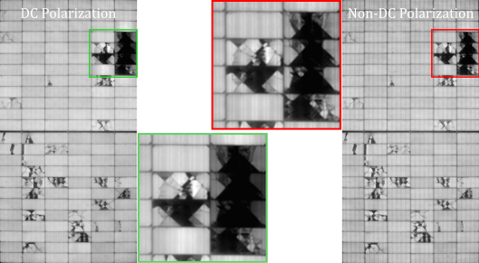
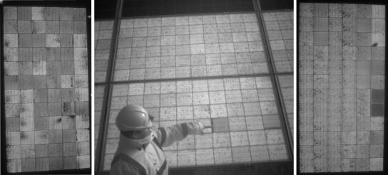
As shown in Figure 4, the images obtained with DC polarisation (left) and non-DC polarisation (right) highlight this contrast enhancement. The green box in the DC image shows visible defects such as cracks, but the overall contrast remains low, whereas the non-DC polarisation image (highlighted with the red box) reveals much clearer details, including subtle defects, such as degradation zones and microcracks.
Comprehensive analysis. Another key advantage of non-DC polarisation is its ability to address a broader spectrum of issues in a single scan, without needing to change the current. By combining effective short-circuit current (Isc RMS) with 10% of Isc RMS, non-DC polarisation ensures that defects requiring different current levels are detected together in one pass. This results in a more comprehensive and thorough analysis of the PV module’s condition, and it reduces the need for multiple testing phases.
An important tool for highlighting the difference between DC and non-DC involves heatmaps, which are visual tools used to represent pixel intensity across the image. By comparing the histogram of pixel intensities, insight into the distribution and severity of defects such as cracks, poor soldering and degradation zones can be gathered. Heatmaps enable us to visually analyse the areas with the most significant changes in intensity, and they can be used to identify microcracks or subtle faults that are not immediately visible in traditional imaging.
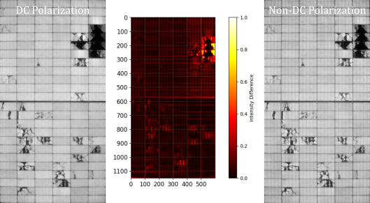
Figure 5 illustrates this comparison using heatmaps. On the left is the DC polarisation heatmap generated from the same images shown in Figure 4. Even though the DC EL highlights visible defects, such as cracks and some soldering issues, its contrast is limited. The non-DC polarisation EL, shown on the right, provides a much clearer representation of the module’s condition by revealing microcracks that are not so clearly visible under DC.
While the heatmap analysis is particularly effective for detecting visible defects, it also excels at revealing latent defects that are not immediately apparent. A prime example is PID, which can be difficult to detect using traditional DC-based EL imaging, especially in its early stages. PID often presents itself as subtle changes in the electrical characteristics of the module, which may not produce strong enough contrast in the traditional EL images. However, by using non-DC polarisation, these subtle defects can be identified with much greater clarity.
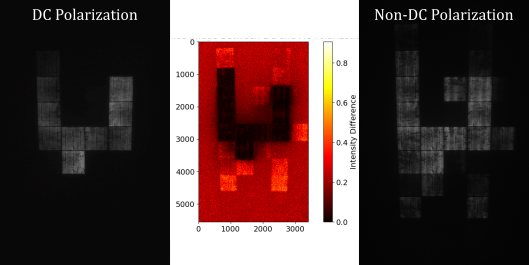
Figure 6 demonstrates this capability by showcasing the detection of PID in a module using the heatmap analysis from non-DC polarisation. The comparison shows how PID, which was nearly invisible in the standard DC EL images, becomes much more noticeable through the heatmap analysis.
Significant progress has been made in the field of EL characterisation for PV modules, but there is still room for improvement. Advancements in techniques such as non-DC EL imaging hold great potential for optimising defect detection and performance analysis in PV systems. These improvements could help further reduce maintenance costs and mitigate the effects of accelerated module degradation.
Improved characterisation methods would enable earlier defect detection and a more precise understanding of module behaviour over time. This, in turn, could reduce maintenance and repair costs, ensuring that photovoltaic plants run more efficiently and profitably. Additionally enhanced monitoring accuracy would also improve module performance and durability, contributing to more reliable and sustainable solar energy production.
Advancements in PV diagnostics
The use of non-DC EL imaging is one of the recent Enertis Applus+ R&D initiatives aimed at improving module diagnostic precision to enhance service quality.
The integration of non-DC EL imaging aims to provide a broader understanding of PV module behaviour, including immediate defects and early indicators of degradation processes that could affect long-term performance. Enertis Applus+ ensures that these tests are carried out exclusively by highly trained personnel, guaranteeing safety throughout the process. This approach not only protects equipment and technicians but also maximises the accuracy and reliability of the results obtained.
Alongside other companies in the sector, we are actively contributing to the continuous improvement of testing tools and methods to help ensure that PV systems meet the high standards of performance, reliability and longevity required by today’s market.
References
[1] Haque, A., Bharath, KVS, Khan, MA, Khan, I. and Jaffery, ZA (June 1, 2019). Fault diagnosis of Photovoltaic Modules. Energy Science and Engineering. John Wiley & Sons Ltd. https://doi.org/10.1002/ese3.255
[2] Zhao, J., Sun, Q., Zhou, N., Líu, H., & Wang, H. (2020). A photovoltaic array fault diagnosis method considering the photovoltaic output deviation characteristics. International Journal of Photoenergy, 2020, 1-11. https://doi.org/10.1155/2020/2176971
[3] Kropp, T., Schubert, M., & Werner, J. (2018). Quantitative prediction of power loss for damaged photovoltaic modules using electroluminescence. Energies, 11(5), 1172. https://doi.org/10.3390/en11051172
[4] Otamendi, U., Martinez, I., Quartulli, M., Olaizola, IG, Viles, E., & Cambarau, W. (2021). Segmentation of cell-level anomalies in electroluminescence imaging of photovoltaic modules. Solar Energy, 220, 914-926. https://doi.org/10.1016/j.solener.2021.03.058
[5] Kropp, T., Berner, M., Stoicescu, L. and Werner, JH (2017). Self-sourced daylight electroluminescence from Photovoltaic modules, IEE Journal of Photovoltaics, 7 (5), 1184-1189. https://doi.org/10.1109/JPHOTOV.2017.2714188
[6] Yamaguchi, S., Yamamoto, C., Ohdaira, K., & Masuda, A. (2018). Comprehensive study of potential‐induced degradation in silicon heterojunction photovoltaic cell modules. Progress in Photovoltaics: Research and Applications, 26(9), 697-708. https://doi.org/10.1002/pip.3006
[7] Spataru, S., Séra, D., Hacke, P., Kerekes, T., & Teodorescu, R. (2015). Fault identification in crystalline silicon pv modules by complementary analysis of the light and dark current– voltage characteristics. Progress in Photovoltaics: Research and Applications, 24(4), 517-532. https://doi.org/10.1002/pip.2571
Authors
Sergio Suárez Sánchez is the global technical manager of testing and optimisation at Enertis Applus+. With more than five years of experience in the PV industry, Sergio is currently taking a PhD in Electronics at UPV/EHU (Spain), an institution involved in the manufacturing of bifacial PV cells, participating in R&D projects as principal researcher, and developing new testing methodologies.
Mario Martínez González is the global technical deputy of testing and optimisation at Enertis Applus+. With more than eight years of experience in both the public and private PV sectors, Mario is currently taking a PhD in PV Solar Energy at UPM/IES (Spain), participating in research projects on the development of new materials and concepts for the PV industry.
José Manuel Rivas Rodríguez is the global operations manager for testing and optimisation at Enertis Applus+. His work focuses on quality assurance and testing methodologies in the PV sector, ensuring the highest standards of performance and reliability.
Sofía Rodríguez is the R&D manager at Enertis Applus+. She has worked on the development of innovative defect detection systems in PV modules, coupled with categorisation and classification techniques. She is currently dedicated to coordinating different research lines in the company.
Daniel Villoslada Fontán is a senior technical manager of testing and optimisation at Enertis Applus+. With more than three years of experience, has participated in multiple QA/QC and R&D projects. Daniel is currently developing and coordinating QA/QC PV projects in Brazil.


