Research shows the ability of PV systems to withstand extreme weather conditions is down to rigorous design. James Elsworth of the National Renewable Energy Laboratory in the US looks at some of the engineering methods for bolstering PV infrastructure resilience in the face of ever increasing climatic and environmental threats.
Try Premium for just $1
- Full premium access for the first month at only $1
- Converts to an annual rate after 30 days unless cancelled
- Cancel anytime during the trial period
Premium Benefits
- Expert industry analysis and interviews
- Digital access to PV Tech Power journal
- Exclusive event discounts
Or get the full Premium subscription right away
Or continue reading this article for free
Extreme weather is the leading cause of power system outages [1]. Extreme weather events are increasing in frequency and severity and climactic conditions are worsening [2]. This will have increasing impacts across the power system, including on solar PV system assets.
PV systems, like other power system infrastructure, are vulnerable to damage and failure from a wide range of threats, including tropical storms, hail and winter weather. PV systems have many advantages over large, centralised power generation assets, but also have their unique vulnerabilities.
PV can and has served as a resilient power source by surviving extreme weather events and delivering power to communities afterwards. There are many examples of this, including [4] and [5]. On occasion, however, PV systems have suffered damage that has prevented them from fulfilling this potential. Much of this damage could have been avoided with better design and installation practices. Many of these practices are simple and inexpensive.
This article focuses on PV structural resilience to extreme weather events, and how best practices for PV system design can promote resilient PV infrastructure and reduce its vulnerability to damage from extreme weather events.
The Why (why have PV systems failed)
While PV can be and has served as a resilient power source, it has failed to do so on occasion. This results in damagedassets, power capacity that cannot be delivered to communities after extreme weather events, and potential reputational damage for the industry.
Sometimes the events causing failures are force majeure type events surpassing what structures were designed to withstand. PV systems sometimes fail during below design level events, though, highlighting areas for design improvements.
PV is a young industry, and design practices haven’t yet matured to match that of many other industries. PV structures are unique, with significant differences from buildings, yet building codes are commonly used as the basis for PV design. The lightweight nature of PV systems, for example, makes them more susceptible to movement and being affected by dynamic loading. This system movement can lead to loading on system components that they aren’t designed to withstand.
All structures have natural frequencies that, if excited, can lead to resonance in the structure. Wind forces can excite these frequencies in PV structures and lead to resonant effects, causing increased movement of the structure and possible structural failure. Tracker systems are especially prone to this [8].
Recurring loads from wind or snow events can degrade PV structures. Design standards, however, typically only stipulate a onetime maximum magnitude event design threshold (i.e., design wind speed) [7]. The impacts are different (e.g., a one-time 115 mph wind gust compared to 90 mph wind gusts six times a year). So, structures aren’t always designed for the loads they will experience.
PV systems are also being installed in new locations, exposing them to more and more varied conditions [6].
There is significant ongoing work aimed at updating PV standards [9] to reduce failure modes, but until PV codes and standards come to maturity and address these issues, it is important to realise that basic design standards aren’t always adequate and that these standards can be misinterpreted by designers. PV project developers and owners can demand more robust, resilient systems by requiring additional specifications and standards beyond the few that are commonly used.
Other factors contributing to PV system damage range from poor installation practices to counterfeit components, though system design is the focus of this article.
The What (what has caused PV systems to fail)
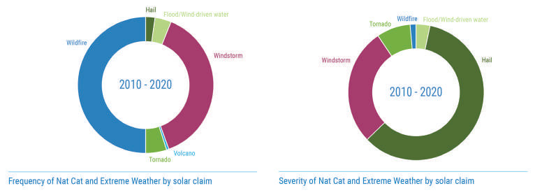
PV systems have survived many types of extreme weather. Windstorms and wildfire are the perils that impact solar PV most frequently, though hail and wind events have caused the largest losses, based on insurance claim data (Figure 1).
Most locations are vulnerable to at least one of the hazards given in Figure 1, making PV design for extreme weather far-reaching.
The Where (where have PV systems failed)
Events that have caused PV system failures are not limited to locations prone to the most extreme weather. Poorly designed and installed PV systems have experienced failures from less severe events, as well. While PV damage is rarely reported or publicised, there are enough examples of failures to be confident that they occur everywhere.
The How (how have PV systems failed)
PV systems are composed of various components that must work together. The two main sub-systems—the structural system and the electrical system— can both suffer damage from extreme weather events.
Structural
The structural system comprises PV modules, racking systems, foundations and all the connections between and within these components. Hail is most likely to impact PV modules. Snow is most likely to cause module or racking failure. Wind can cause impacts to all components, especially the structural connections.
Structural connections in PV systems typically consist of nuts, bolts and clamps that connect modules to the racking structure, racking elements to each other, and the racking structure to the foundations or roof. Module attachments have been the most common failure mode in numerous events [11, 12, 13].
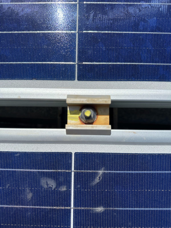
There are two main approaches to attaching modules to the racking: clamp systems and direct bolting. Clamp systems typically apply a clamping force from the top of the module frames at four or more points on the module. One clamp typically holds two adjacent modules (Figure 2).
Top clamp products vary significantly in several ways:
• The amount of contact area between the clamp and the top of the module frame. Small contact areas make it easier for modules to come free of the clamps.
• The amount of contact area between the clamp hardware (bolt head or nut) and the rail in the support structure. Small contact areas can lead to bolt heads or nuts tearing out of the rail slots.
• The amount of rotation that is needed to release the clamp hardware from the rail slot. Some clamps have small bolt heads that slot into wide rail gaps that can rotate out of the rail easily (after only 45-65° of rotation). System vibrations or poor initial torquing can allow this rotation.
Each of these three are places where top clamps have failed. Determining exact minimum specifications for these three clamp parameters is an area where future work is needed, but designers should consider them when selecting between different products.
Top clamps also typically hold adjacent modules simultaneously. This means that if one module comes loose or is damaged, then the adjacent module may no longer be held securely, and it can then come free. The same can then happen for the subsequent module. The result is that an entire row of modules can be lost because of one point of failure (Figure 3).
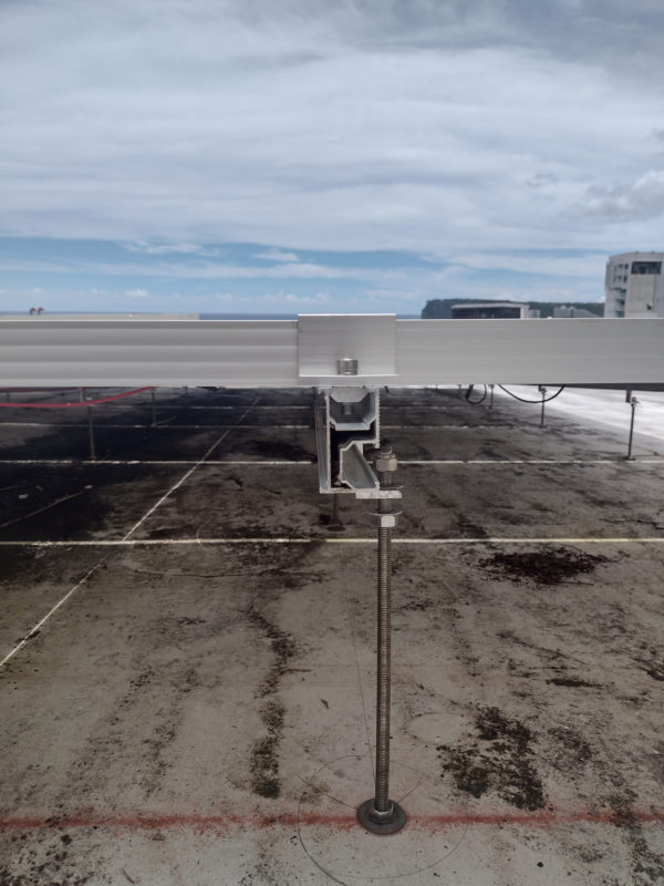
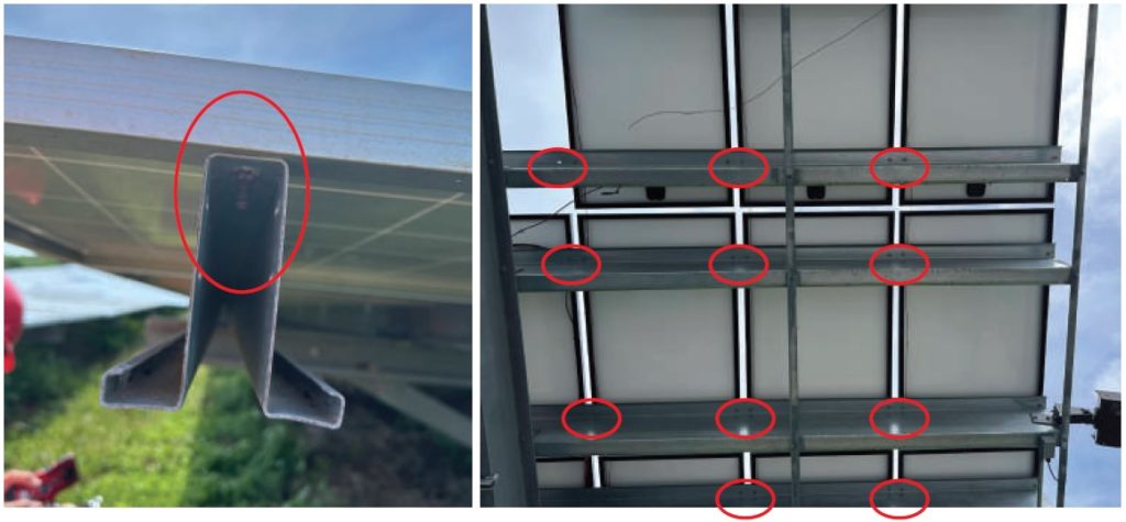
Through-bolting is where the module is directly bolted to a racking rail below (Figure 4). Compared to clamping, bolts aren’t shared between modules, so there is no chance of progressive failure. The bolts also cannot simply rotate out of rail slots. Through-bolting can be difficult, however, for rooftop systems where installing bolts under modules may be impractical. There is also more labour time involved in through-bolting. The most common through-bolt failure is bolts tearing out of either the racking rail or module frame.
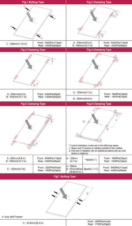
The location of the module attachments has a significant impact on the load ratings of the modules. Module installation manuals give load ratings for various mounting locations. Figure 5 shows that for one module, the uplift load rating can be as high as 4,300 Pa or as low as 1,600 Pa based on mounting location. Some sites assume top load ratings despite not mounting modules in the locations that will achieve these load ratings.
Certain features of PV racking systems can also contribute to PV system failures, especially from wind events. Racking with high tilt angels or systems that mount panels high above the ground or roof surface are particularly prone to wind damage. Many racking systems use thin gauge steel and are only designed to resist upward and downward loads. These are vulnerable to damage from loading along other axes.
Meanwhile, tracker systems have failed several ways. Moment forces on the torque tube have caused failures, especially at splices between sections of torque tube. Modules on tracker systems are also typically attached closer to the centre of the module. This overhang means the top and bottom of modules are susceptible to damage from wind and snow load forces at the edges of the modules they aren’t rated to withstand. Load ratings are lower as a result (Figure 5, bottom).
Electrical
Much of PV design for extreme load conditions focuses on module load ratings. PV system failures, however, are usually not a result of module loading failure, suggesting that other system-level considerations should take design priority.
Electrical systems on PV structures are also vulnerable to damage from extreme weather. Water ingress into electrical enclosures and conduit has caused failures. Insufficient wire management systems can leave cables and PV connectors dangling where winds and water can cause damage.
How to design (more) resilient PV infrastructure
A resilient solar PV system is one that can withstand the conditions it will experience in the field. While resilient PV design is site-specific, there are some principles that apply for designing systems to be resilient to specific threats.
High wind resilient PV design recommendations
Layout Where possible, install large fixed-tilt ground-mounted systems at low tilt angles, low to the ground, with front and rear support posts and cross bracing [14]. Do not install PV modules in corner zones on roofs. See SEAOC PV 2-17 for guidance [15].
Module attachments Through-bolt modules to the racking if feasible, using washers large enough to prevent bolt tear out. For more information on these types of fasteners, see [11]. If using top clamp module attachments, choose clamps that hold modules individually. Select clamps with greater surface clamp area (both on the module frame and on the racking) that cannot easily rotate out or tear out of the racking [14]. Additional module attachment points help and can give the modules higher load ratings. Six mounting points are sometimes used in areas with higher design wind loads but may require the installation of an additional racking rail. More attachment points don’t necessarily increase resilience if the attachment is poor to begin with [11].
Bolted Joints Torque all system bolts as specified and perform a torque inspection annually [11]. Use locking hardware on bolted joints to prevent loosening. Lock bolts, wedge-lock washers, Belleville washers, thread lock, and nylon inserts can all help. Do not use split washers [11]. All structural connections shall be designed to be slip-critical and redundant, avoiding single points of failure. [16]
Racking The overall goal of the racking structure should be to reduce movement and vibration in the system and transmit loads to the ground or roof. The structure should be designed for dynamic loading and resonant effects. See SEAOC PV 2-17 for guidance [15]. Racking systems should make modules part of the load path. Racking systems should be braced laterally and longitudinally to transmit forces from all directions to the ground or roof. Front and rear posts increase system stiffness and reduce system movement [13].
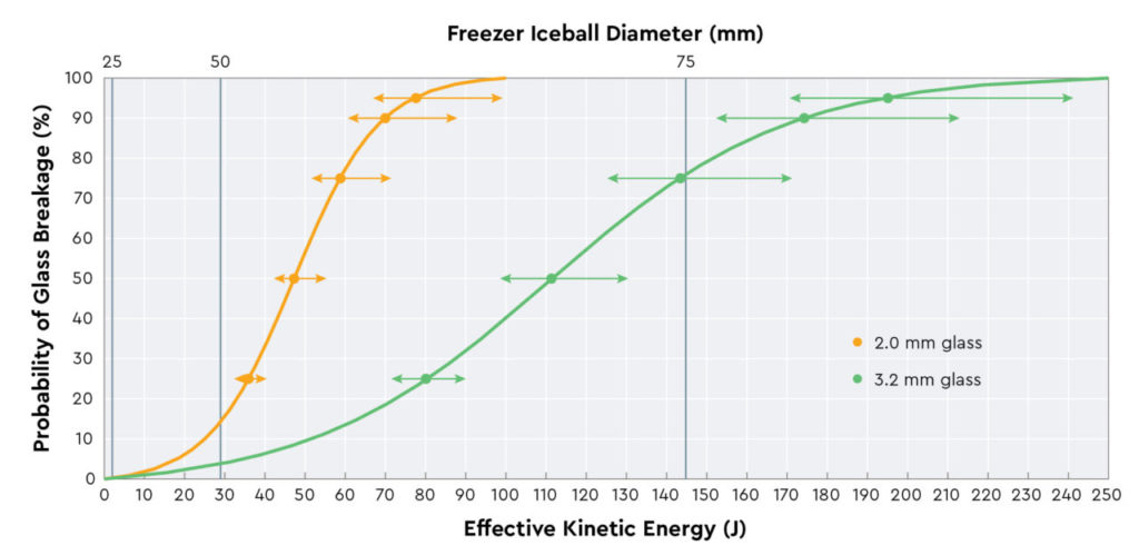
Modules Smaller modules – 60-cell or equivalent – should be used for rooftops or places with hurricane risk. 72-cell or equivalent are adequate for ground-mounted systems; avoid larger format modules in high wind regions. Modules with 3.2 mm front glass or thicker should resist fracture from flying debris better than those with 2.0 mm glass [17]. Ensure modules are mounted in accordance with the installation manual to give the desired load ratings [11]. Select modules with the highest uplift load ratings – 4,000 Pa or higher – in high wind risk locations [11].
Electrical Use NEMA 4 or 4X rated enclosures on all electrical boxes. Enclosures should also be gasketed, with locking hinges designed to prevent water intrusion from driven rain. Enclosures should have weep holes, be mounted on a vertical surface with conduit entering from the bottom, and designed to prevent water intrusion should water get into the conduit above the enclosure [16].
Mount electrical enclosures above 500-year flood and storm surge levels [11]. Use durable wire management devices, such as those made specifically for PV wire routing. Plastic or nylon wire ties are unreliable; even UV exposurerated ties aren’t adequate. Should wire management fail, wires and PV connectors can dangle or lay on the ground or roof, prone to damage from water, animals, or wear from wind gusts [11].
Ensure cables are not taut against sharp edges of conduit or module frames. Sharp edges can wear through cable insulation through thermal expansion cycles, wind gusts, or gradual system movement over time [11].
Hail
PV systems have fared well in hailstorms, though some very large events have damaged PV systems. Hail has been the greatest contributor to insured losses on PV systems worldwide [6]. To help increase resilience of PV systems in areas prone to severe hail:
Modules Select modules with 3.2mm or thicker front glass (Figure 6) [17]. Select modules with frames, the thicker the better [19]. Select smaller modules, such as 60-cell or equivalent [18].
Minimum hail certification and lab tests are not sufficient. Require that modules pass a more stringent test, such as the IEC TS 63397 tests for 50mm hail, FM Global Standard 4478, RETC’s Hail Durability Test, or PVEL’s Hail Stress Sequence [18].
System considerations For fixed-tilt systems, higher tilt angles reduce the likelihood of a direct impact [20]. For trackers, select a system with a “hail stow” mode that rotates modules to maximum tilt in hail events. Engaging stow typically takes minutes and communications and controls need to be fully functioning to engage [20].
Pre- and post-storm Some hail damage may not be obvious. Hail can cause microcracks that can hurt production over time. Conducting pre-storm baseline and post-storm imaging of panels allows a complete storm damage assessment.
Snow and winter weather
Winter weather events bring snow accumulation and ice. Best practices to avoid winter weather event damage include:
Modules Select modules with front test load ratings of at least 5,400 Pa, when mounted in accordance with the installation manual. Additional mounting points can increase the load rating [21]. Employ IEC 62938 standard for non-uniform snow loads [22]. Use smaller modules [21]. Orient modules in landscape to allow for greater production as snow melts off the top and middle thirds of modules.
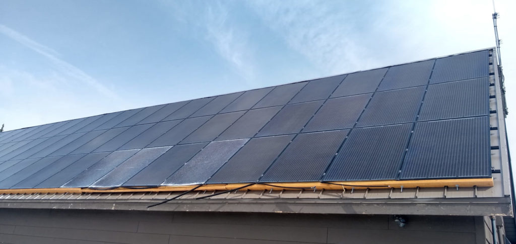
Frameless modules allow snow to slide off the modules more easily. In some cases snow and ice loads have forced the bottom frames off of PV modules (Figure 7). Frameless modules often aren’t rated to withstand loads as high as framed modules. Load rating should take precedence over the framing [23].
Racking and tilt angle Higher tilt angles allow snow to shed off modules more easily. Select tilt angle considering increased wind loads that come at higher tilt angles [24]. Elevate system so that modules are high enough to give room for accumulation of shedded snow underneath. Allow at least two feet above maximum normal snow depth [21]. Trackers with a “snow stow” mode can reduce snow buildup on modules and allow faster shedding [21]. Ice formations on structures can cause additional loading on racking, cables, and other components. Categorise solar racking and components as “ice-sensitive structures” and follow according ASCE 7 guidance [7].
Foundations Freezing and thawing grounds in cold climates can lead to forces on foundations that push them up out of the ground. Design for this “frost heave,” even though it isn’t required in most building codes. Consider frost depth in determining the depth of the foundation. [25] provides guidance for frost heave calculations for solar PV systems.
Site considerations Install perimeter markings around arrays where snow may accumulate and bury an array. This will help prevent damage from snow removal crews or vehicles [21].
Construction Even the most robust, resilient PV system design can be totally negated with poor installation. A challenge lies in creating design specifications that limit room for installer error or procurement of unspecified components.
O&M While design and installation of PV systems will have the most impact in extreme weather resilience, operations and maintenance activities can keep systems in good shape and identify vulnerabilities that may be exposed in extreme weather. Regular activities include:
• Visual inspections for loose cables, taut cables, modules with broken glass, and deformed modules or racking.
• Structural bolt torque audits on the module attachments and racking structure to ensure bolts haven’t loosened. Workers should be trained on how to properly torque check bolts and tighten them to torque specifications (not too tight or too loose) using a calibrated torque wrench [11].
• Testing of tracker stow systems and controls.
• Thermal or EL imaging of system to identify invisible damage and vulnerabilities. These can serve as a baseline to reference after any damage from future events.
Post-event After a storm or other extreme weather event, clean up the site to remove any modules or other debris which could cause damage in a subsequent storm. Do a visual inspection and record damage to all system components. Perform electrical string-level testing of open circuit voltage and short circuit current before repowering the system. Perform thermal or EL imaging.
Case Studies Guam – Typhoon Mawar
Typhoon Mawar struck Guam in May 2023, reaching sustained wind speeds of up to 140 mph and causing damage to PV systems and other infrastructure. Findings from post-storm PV damage assessment of 29 PV systems can inform resilient PV design globally. There were systems with no apparent damage, as well as systems that were completely lost, with those two cases sometimes occurring on neighbouring arrays [14].
Failures were most commonly the result of:
• Inadequate module clamping;
• Module clamps rotating out of underlying support rail. This often led to cascading failure;
• Debris impact on modules resulting in a fracture;
• Excessive tilt angle (greater than 5 degrees increased risk).
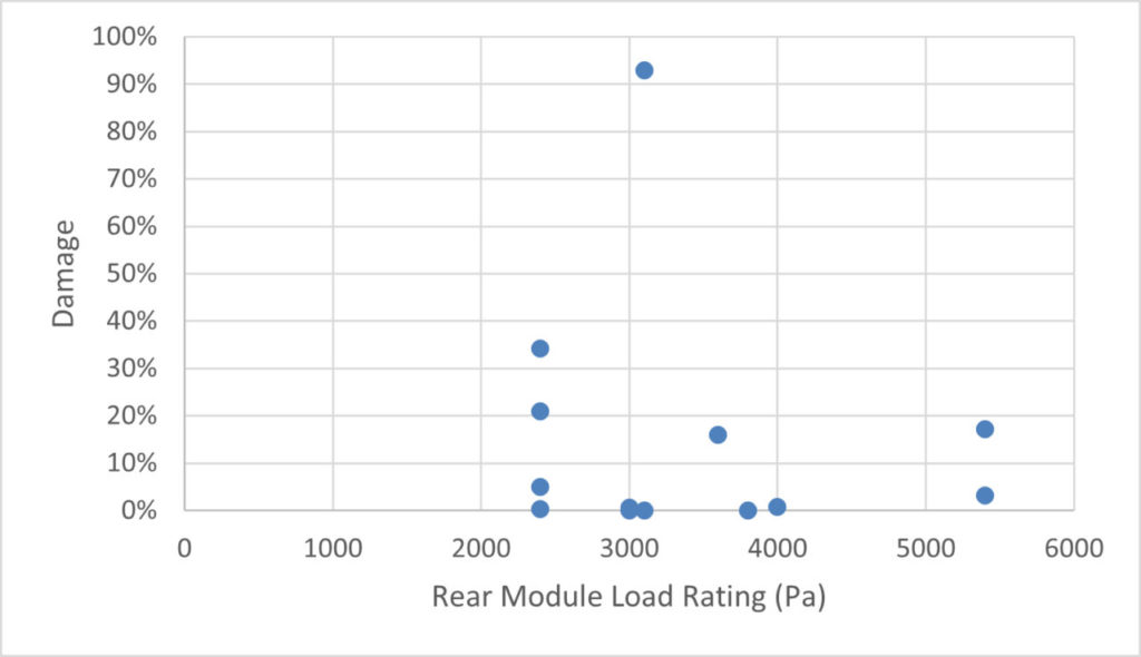
There was no clear evidence of modules failing due to direct high wind loading, despite how much focus in PV wind design is given to module load ratings. Other structural system failures were far more prominent, suggesting modules load ratings should be a secondary wind load design consideration. To further support this, module load ratings show no correlation to system damage (Figure 8).
Percentage of missing or broken modules was used to estimate the failure rate on each system, summarised in Table 1.
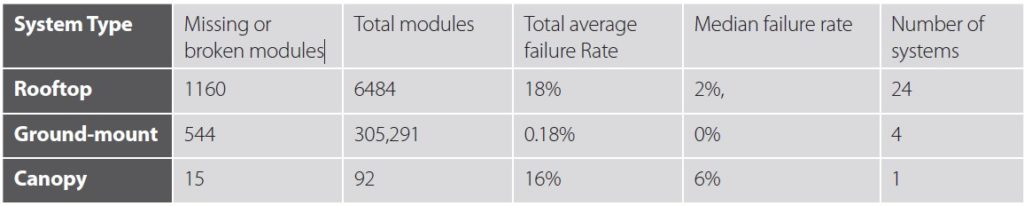
Rooftop damage is inflated by a handful of systems that experienced total loss. Of the 25 rooftop systems observed, 17 had less than 5% damage. Two of the ground-mounted systems were in locations that experienced lower wind speeds. On the canopy system, the structure was undamaged, but module attachments tore out of the frames.
Interestingly, wind speed did not appear to be a determining factor in how much damage systems suffered (Figure 9). Several systems experiencing gusts above 180 mph survived completely, while some systems that had gusts of 140 mph were substantially damaged.
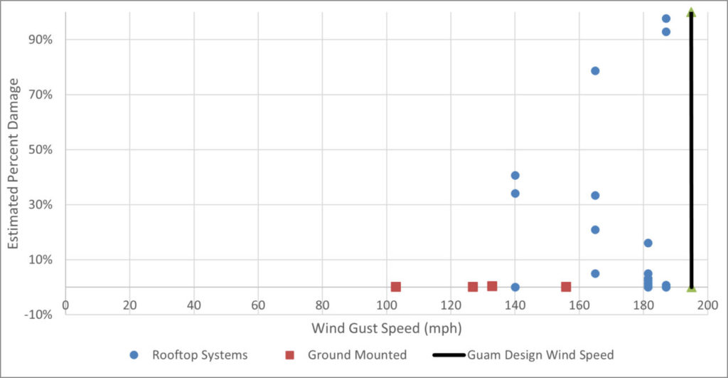
This implies that system design and installation, rather than wind speed, determined the extent of damage. This is encouraging; if PV is designed well, it can survive extreme wind events. Systems that performed best on Guam:
• Were ground-mounted or mounted very close to the roof. On flat roofs, surviving systems typically had tilt angles of 4-5°.
• Used through-bolting or clamping systems with a larger bearing surface (0.4-1.2 in2 per clamp) or used continuous clamping systems along the entire long edge of modules.
• Used clamping systems that use a “T”-bolt that must rotate 90 degrees to come free from racking, rather than bolts that could rotate free with less rotation (~60°).
• Did not feature modules near the corners of roofs.
• Had racking systems made of thicker gauge components with significant cross-bracing.
As a remote island with 100% clean energy targets, it is paramount that PV installed in Guam learn from these lessons and heed these recommendations to be resilient to future tropical storms.
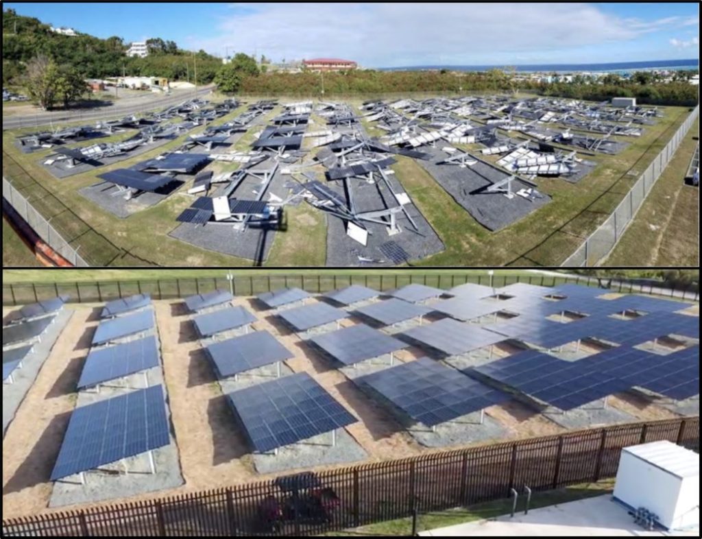
St Croix, US Virgin Islands – Hurricane Maria
Hurricanes Irma and Maria struck St. Croix in the US Virgin Islands within weeks of each other in September 2017 as Category 5 and 4 storms. One PV system, a 469kW fixed-tilt ground-mounted system was destroyed.
While the conditions in the storm were extreme, a post-storm damage assessment revealed that there were design features and installation practices that led to more damage than was necessary [26], including “lack of beam stiffness, inadequate clamp and fastener use, reliance on outdated codes, and improperly selected electrical enclosures”. Wind speeds on the site were lower than the design wind speed of the system.
Before reconstructing the array, an engineering firm was contracted to analyse wind loading at the site and develop specifications for the rebuild.
This analysis led to the installation of a PV array that will be much more resilient in the face of future events (Figure 10).
The engineering analysis began with an analysis of PV design codes and where gaps existed that led to these failures.
A major gap was that the current codes only required design for static loading— mechanical loads of a fixed magnitude and direction. Wind loading, however, can be dynamic—the load can vary in magnitude and direction, cause turbulence within the array, and can cause system components to sway. Dynamic loading can impart loads on PV systems that they were not designed to withstand, leading to component failure. Dynamic loading can also cause failures by exciting natural frequencies inducing resonance.
The engineering team applied dynamic loading calculations and guidance from SEAOC PV2-2017 [15], analysed the resonant frequencies of various PV system designs and built computational fluid dynamics (CFD) models to find maximum pressure on PV modules under various system designs.
The resonant frequency analysis showed that the proposed tilt angle of 5° was prone to resonance from wind loads. Steeper pitches mitigated the likelihood of wind-induced resonance. Too high a tilt angle, however, led to greater direct wind loading and higher pressures on the panels. A compromise of 12° yielded the lowest overall loads for this specific array and avoided resonance that could occur at lower tilt angles while keeping wind pressure on the panels under their rated loads.
Other design features that helped increase the robustness and resilience of this array included front and rear support posts, locking fasteners, modules with high published load ratings, and lowering the array by one foot compared to standard design.
More detailed information on the array and rebuild can be found at “Toward Solar Photovoltaic Storm Resilience: Learning from Hurricane Loss and Rebuilding Better”.
Conclusion
As seen through various examples of systems surviving and failing, often in the same events, it is the characteristics of the system that ultimately have determined survivability, not the magnitude of the event. This should be encouraging, because it is possible to design PV systems that can survive extreme events. Given the current state of codes and standards and relative inexperience of designers in this young industry, however, this may require additional project requirements above the typically required standards. These additional requirements aren’t necessarily overburdensome or costly. Little things can make big differences. Following good design fundamentals, down to the literal nuts and bolts, is essential for designing and building resilient PV that can power communities after extreme weather events.
Author
James Elsworth is a mechanical engineer and researcher at the United States Department of Energy’s National Renewable Energy Laboratory. His work focuses on assessing and promoting resilience at all scales, from country-wide power system resilience down to the (literal) nuts and bolts of PV system infrastructure. He specialises in hardening solar PV systems for locations experiencing extreme environmental conditions such as hurricanes and high wind events.
References
[1] U.S. Dept. of Energy. 2016, “Electric disturbance events,” U.S. Department of Energy Office of Electricity Delivery and Energy Reliability, 2016. http://www.oe.netl.doe.gov/oe417.aspx
[2] NASA. “Extreme Weather and Climate Change,” NASA Global Climate Change. https://climate.nasa.gov/extreme-weather/
[3] Hotchkiss, Eliza, Alex Dane, and Connie Komomua. 2018, “Resilience Roadmap,” National Renewable Energy Laboratory (NREL), 2018. https://www.nrel.gov/resilience-planning-roadmap/
[4] De la Garza, Alejandro. 2023. “In Puerto Rico, a Small Town Takes Climate Action Into Its Own Hands.” Time. March 20, 2023. https://time.com/6264631/puerto-rico-adjuntas-solar-microgrid/
[5] Sherriff, Lucy. 2023. Babcock Ranch: Florida’s first hurricane-proof town. BBC.com. 4th September, 2023. https://www.bbc.com/future/article/20230904-babcock-ranch-floridas-first-hurricane-proof-town
[6] GCube Insurance. 2021. “Hail or High Water: The rising scale of Extreme Weather and Natural Catastrophe losses in Renewable Energy.” Q1 2021 Report.
[7] American Society of Civil Engineers, 2022. “ASCE/SEI 7-22: Minimum Design Loads and Associated Criteria for Buildings and Other Structures (ASCE/SEI 7-22).”
[8] Roedel, Alex and Stuart Upfill-Brown. 2018, “Designing for the Wind: USING DYNAMIC WIND ANALYSIS AND PROTECTIVE STOW STRATEGIES TO LOWER SOLAR TRACKER LIFETIME COSTS.” NexTracker, A Flex Company, 2018. https://info.nextracker.com/nextracker-designing-for-thewind
[9] Manning, Jon PE and Steve Gartner, PE. 2021, “New ASCE committee will focus on advancing the reliability of solar PV structures,” PV Magazine, June 25, 2021. https://pv-magazine-usa.com/2021/06/25/new-asce-committee-will-focus-on-advancing-the-reliability-of-solar-pv-structures/
[10] World Risk Index. 2022, “Worldmap of Risk 2023,” https://weltrisikobericht.de/en/#:~:text=The%20WorldRiskIndex%20indicates%20the%20disaster,mean%20of%20exposure%20and%20vulnerability
[11] Elsworth, James and Otto Van Geet. 2020. Solar Photovoltaics in Severe Weather: Cost Considerations for Storm Hardening PV Systems for Resilience. Golden, CO: National Renewable Energy Laboratory. NREL/TP-7A40-75804. https://www.nrel.gov/docs/fy20osti/75804.pdf.
[12] Burgess, Christopher, Sanya Detweiler, Chris Needham, and Frank Oudheusden. 2020, “Solar Under Storm Part II: Select Best Practices for Resilient Roof-Mount PV Systems with Hurricane Exposure,” Rocky Mountain Institute and Clinton Foundation. https://rmi.org/insight/solarunderstorm/ and www.clintonfoundation.org/Solar-Under-Storm.
[13] Burgess, Christopher, and Joseph Goodman. 2020, “Solar Under Storm: Select Best Practices for Resilient Ground-Mount PV Systems with Hurricane Exposure,” Rocky Mountain https://rmi.org/insight/solarunder-storm/
[14] Elsworth, James, Otto Van Geet, Chuck Kurnik, and James Salasovich. 2023, “Solar Photovoltaic Damage Assessment after Typhoon Mawar: Findings and Recommendations for Resilient PV on Guam” U.S. Department of Energy’s National Renewable Energy Laboratory. Confidential: Not available for public release. Public release version forthcoming.
[15] Structural Engineers Association of California. 2017. “Wind Design for Solar Arrays.” https://www.seaoc.org/content.aspx?page_id=586&club_id=32108&item_id=18912
[16] U.S. Department of Energy’s Federal Energy Management Program. “Technical Specifications for On-site Solar Photovoltaic Systems.” https://www.energy.gov/femp/technical-specifications-sitesolar-photovoltaic-systems
[17] RETC. 2022, “2022 PVMI Report,” https://retc-ca.com/download-2022-pvmi
[18] U.S. Department of Energy’s Federal Energy Management Program. 2023, “Hail Damage Mitigation for Solar Photovoltaic Systems.” https://www.energy.gov/femp/hail-damage-mitigation-solar-photovoltaic-systems
[19] Wormser, Paul. 2020, “Investment Confidence,” Clean Energy Associates. https://www.pv-magazine.com/wp-content/uploads/2020/12/02_Paul-Wormser_CEA.pdf
[20] Roedel, Alex and Kent Whitfield. 2020, “Mitigating Extreme Weather Risk PART 1: Understanding How Differentiated Design and Control Strategies Unlock New Opportunities for Solar Development,” NexTracker, Inc. https://info.nextracker.com/mitigating-extreme-weather-risk
[21] U.S. Department of Energy’s Federal Energy Management Program. 2023, “Solar Photovoltaic Hardening for Resilience – Winter Weather.” https://www.energy.gov/femp/solar-photovoltaichardening-resilience-winter-weather
[22] International Electrotechnical Commission. 2020, “IEC 62938:2020 Photovoltaic (PV) modules – Non-uniform snow load testing, “ IEC TC 82 2020. https://webstore.iec.ch/publication/33027
[23] Per-Olof A. Borrebaek, Bjorn Petter Jelle, Zhiliang Zhang. 2019, “Avoiding snow and ice accretion on building integrated photovoltaics – challenges, strategies, and opportunities,” Solar Energy Materials and Solar Cells, Volume 206, March 2020, 110306. https://doi.org/10.1016/j.solmat.2019.110306
[24] Powers, Loren, Jeff Newmiller, and Tim Townsend. 2010, “Measuring and modelling the effect of snow on photovoltaic system performance,” IEEE, 2010 35th IEEE Photovoltaic Specialists Conference. https://ieeexplore.ieee.org/document/5614572
[25] Newson, T. and Hammad, M. 2022, “Solar Foundation Design in Cold Climates, “ GeoCalgary 2022, October 2-5, 2022. https://geocalgary2022.ca/wp-content/uploads/papers/235.pdf
[26] Elsworth, James, Otto Van Geet, Gerald Robinson, Ghazi Bari, Jonathan Calton, John Hickey, Erin Morrison, Kelly Payne, and Kurt Lyell. 2023. Toward Solar Photovoltaic Storm Resilience: Learning from Hurricane Loss and Rebuilding Better.” U.S. Department of Energy’s Federal Energy Management Program. Feb 6, 2023. https://www.energy.gov/femp/articles/towardsolarphotovoltaic-storm-resilience-learning-hurricane-loss-and-rebuilding
[27] U.S. Department of Energy’s Federal Energy Management Program. 2023, “Successful Deployment of a Solar Power System at Mount Rainier National Park.” https://www.energy.gov/femp/successful-deployment-solar-power-system-mount-rainier-national-park


