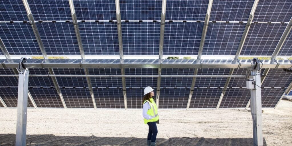
PV systems combining bifacial and tracker technologies deliver the lowest-cost PV-generated electricity in most parts of the world. Joshua Stein, Giosuè Maugeri, Silvana Ovaitt and Thore Müller explore some of the technical and financial factors influencing the optimal performance of tracked bifacial PV systems.
In August 2024, the International Energy Agency (IEA) Photovoltaic Power Systems (PVPS) programme published a new report entitled, “Best Practices for the Optimization of Bifacial Photovoltaic Tracking Systems.” This report includes two industry surveys, numerous interviews and a PV performance model intercomparison. This article provides a high-level summary of highlights from the report.
Try Premium for just $1
- Full premium access for the first month at only $1
- Converts to an annual rate after 30 days unless cancelled
- Cancel anytime during the trial period
Premium Benefits
- Expert industry analysis and interviews
- Digital access to PV Tech Power journal
- Exclusive event discounts
Or get the full Premium subscription right away
Or continue reading this article for free
Bifacial PV tracking systems have become the predominant configuration for utility-scale PV systems globally and this technology is still evolving. Bifacial PV technology has rapidly overtaken the cell and module market share. According to the 2024 International Technology Roadmap for Photovoltaic (ITRPV), 90% of cells produced in 2024 are bifacial, and about 95% of modules use bifacial cells with 62% made as bifacial modules with the rest being used in monofacial modules. This fraction is expected to reach 73% by 2034 [1].
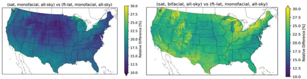
60% of the market share for PV systems are installed on trackers. A 2020 technoeconomic study [2] showed that bifacial, single-axis tracked systems offer the lowest levelised cost of electricity (LCOE) for 94% of the global land area. On average, these systems exhibit a 16% lower LCOE and up to 35% higher energy yield compared to fixed-tilt monofacial PV systems. Figure 1 illustrates the simulated yield differences between single-axis tracking (SAT) and monofacial latitude-tilt systems across the United States. SAT systems increase annual yields by 15-20%, while adding bifacial modules results in an additional 2-10% absolute increase. Notably, the gains from bifacial modules and trackers are additive, with the most significant relative increases observed in regions with substantial snowfall.
Two surveys were conducted, one of 16 tracker companies, representing over 87% of the global market share from 2012-2021 and a second that focused on PV system owners, operators and O&M technicians, representing 13.4GW of bifacial tracked PV systems worldwide. Results of these surveys along with an extensive literature review are discussed in the report.
SAT tracker types and anatomy
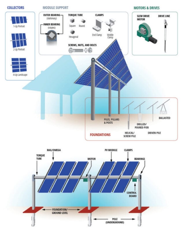
Horizontal SATs’ key components and features (Figure 2) include torque tubes attached to bearings and motors, mounted on posts or piles anchored to a solid foundation. The foundation’s features are customised based on site-specific geotechnical conditions, soil type, and wind loading calculations. Purlins, rails, or omegas are attached to the torque tube to mount the PV modules using clips or bolts. SAT configurations vary by the number of modules mounted perpendicular to the torque tube. For instance, bifacial systems prefer portrait orientations (1P, 2P, etc.) because modules are designed to be mounted along their long edges. In contrast, landscape orientations (2L, 4L, or 6L) require two purlins to cross the back of each module, which can reduce rear-side irradiance and bifacial gain.
Most trackers are driven by DC motors powered directly from PV and batteries, with 1-2 tracker rows driven by a single motor. Alternatively, a single high-power AC motor can drive up to 32 connected rows that move together. The maximum tracker tilt angle is generally 55° to 60°. Two companies reported a maximum tilt angle of 90° to support their use in agrivoltaic applications.
SAT rows are typically aligned with a north-south axis, varying the tilt from east in the morning to west in the afternoon. The spacing between tracker rows, or pitch, is determined by the ground coverage ratio (GCR). Higher GCR values can increase energy production per land area but may lead to increased row to-row shading and reducing overall efficiency. Backtracking can minimise self-shading but may result in non-optimal tracking angles and lost energy.
Tracking algorithms and controls in SAT systems
Tracking algorithms have evolved over time. The oldest algorithm, called true-tracking, rotates all rows to minimise the incidence angle between the Sun and the array and the normal vector to the plane of the array (POA). This method results in row-to-row shading early and late in the day [3]. Backtracking, on the other hand, adjusts the tracking angle of all rows towards horizontal in the morning and evening to prevent row-to-row shading [4]. This method has been widely adopted in commercial single-axis trackers since 2020.
Slope-aware backtracking extends the backtracking algorithm to consider axis tilt and cross-slope topography, making it suitable for sites with mono-sloping terrain [5]. Recent advancements have applied this model to rolling 2D terrain, allowing for partial-tracking strategies in complex 2D terrain [6]. Non-analytical methods such as ray-casting have been proposed for calculating optimised backtracking angles in complex 3D sites [7]. Half-tracking allows half-cell modules to be half shaded during morning and evening to gain as much as 1.7% more energy [8]. Diffuse-response algorithms orient the modules to horizontal when skies are cloudy to capture more diffuse light [9]. Self-cleaning algorithms tilt the modules during precipitation events to allow water to wash away dirt or snow. Hail-response and wind-response algorithms orient the rows to protect the modules from damage [10].
Albedo, the measure of a surface’s reflectivity, is key to bifacial PV plant performance. Natural ground albedo ranges from 10% to 30%, varying with soil, vegetation and season. Light reflected from the ground onto the rear side of bifacial modules boosts energy production, contributing to bifacial gain.
Albedo optimisation involves placing high-albedo materials, such as white geosynthetics, on the ground to increase reflected light and thus bifacial gain. Common albedo enhancers include durable polymeric materials such as geotextiles and geomembranes, as well as other materials such as sand, shells, salt and calcium-based spray coatings. These materials typically have albedo values ranging from 60% to 75%, significantly higher than natural ground albedo.
The decision to use albedo enhancers depends on whether the additional energy produced justifies the cost of the materials and their maintenance. Material prices range from US$1-2 per square meter, and covering the entire ground may not be economically feasible unless additional benefits, such as vegetation control, offset the costs. Research suggests that placing albedo enhancers directly below the modules is most effective [11]. Albedo enhancement affects inverter clipping and system degradation and over time, as module efficiency decreases due to degradation, can partially compensate for lost capacity.
Albedo enhancers present several operations and maintenance (O&M) challenges. Soiling can reduce the reflectivity of the material, diminishing energy gains. Geosynthetics can degrade due to UV exposure and attachment failures can lead to tearing or wind-induced damage. Some materials pose operational hazards and can be an optical nuisance for O&M crews. Sustainability considerations include material composition, recyclability, water runoff properties and the impact on local vegetation and wildlife. Despite the potential benefits, the feasibility of albedo enhancement is not yet clear. A survey of tracker companies identified only one company reporting client projects that use or test these materials.
Agrivoltaic applications
The dual use of land for both agricultural production and photovoltaic (PV) energy generation is another application for bifacial PV tracking systems that is gaining interest around the world. Trackers in agrivoltaic applications can expand the areas suitable for PV installation and offer additional value to farmers, including additional income as well as potential crop yield increases and enhanced community acceptance of clean energy. A survey of tracker companies revealed that 11 out of 16 companies develop trackers for agrivoltaic applications, reporting a cumulative tracker sales volume of 19GW in 2022 across 20 countries. Common design modifications for agrivoltaics include increased tracker height, wider row spacing, modified tracking algorithms, integration of agricultural sensors, and the ability to move PV arrays to 90° tilt during agricultural tasks. Strategies to improve soil moisture homogeneity, such as tilting the PV array during precipitation events, can enhance grassland productivity and soil moisture distribution.
Several agrivoltaic test sites are experimenting with different PV designs and technologies paired with various crops. Examples include European Energy’s testing of different tracker positions for crop sowing in Denmark, Fraunhofer ISE’s elevated SATs for larger farm machinery and higher crops in Germany, and Jack’s Solar Garden in Colorado, which features 8ft tall trackers to facilitate tractor usage. Early results from NREL’s agrivoltaic test bed in Colorado indicate greater agricultural yields from crops under the trackers compared to controls.
Monitoring tracked bifacial PV
The IEC 61724-1 standard specifies the equipment and methods for monitoring PV system performance, with requirements for utility-scale systems (Class A) and rooftop/commercial systems (Class B). For bifacial tracked systems, considerations for rear POA irradiance and albedo are included.
Irradiance sensors, including those measuring horizontal, front and rear POA irradiance, should be placed to provide a representative view of field conditions, avoiding shadows from objects like trees and power lines. In large PV plants, periodic cross-checks of sensors against redundant or reference devices are recommended to identify issues such as soiling, faults or calibration errors. Maintenance should include weekly cleanings, replacement of faulty sensors with recalibrated units, on-site checks with reference instruments and, for Class A systems, sensors should be re-calibrated every two years or as recommended by the manufacturer. Conflicts of interest can arise if a single contractor is responsible for both maintaining high solar plant efficiency and high-quality irradiance data [12].
The IEC 61724-1 standard advises sensor placement to minimise shading and accurately capture rear-side irradiance. It recommends multiple sensors along the module array’s transverse line. Class A bifacial PV systems require three times more backside irradiance sensors than frontside sensors, with quantities based on system size.
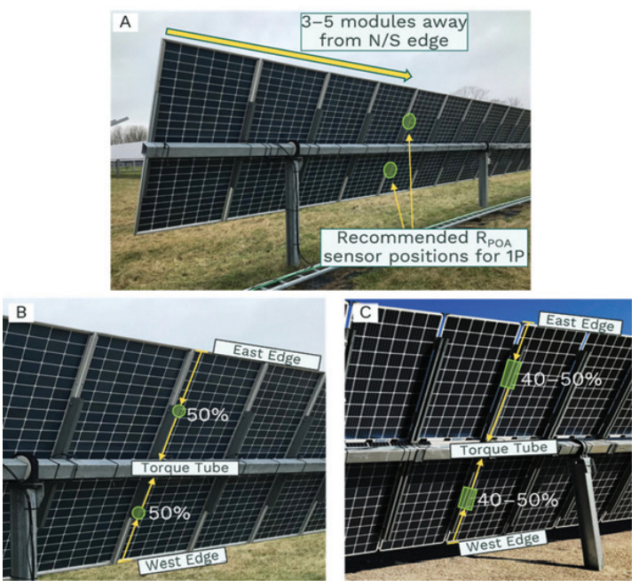
Research has identified optimal sensor positions for both frontside [13] and backside irradiance measurements [14, 15]. For front side POA irradiance sensors on SATs, positions should be representative of the annual average irradiance, avoiding array edges where irradiance can be higher or lower due to obstructed views. For rear POA irradiance sensors, recommended positions include placing sensors 3-5 modules away from the north or south edge and mounting them on the transverse beams (purlins) for 1P systems or slightly closer to the edges for 2P systems (Figure 3).
An alternative method to measuring the effective irradiance reaching the array is to use calibrated bifacial reference modules [16-17]. However, small-area sensors like thermopile pyranometers or c-Si reference cells remain more common due to their codification in standards. Ongoing research and field validation are essential to refine these methods and ensure accurate performance monitoring in diverse PV system configurations.
Back-of-module temperature (TMOD) is crucial for assessing PV system performance but presents challenges due to inter-module temperature non-uniformities and ensuring good thermal contact between the TMOD sensor and module surface. For bifacial modules, TMOD sensors and cabling inevitably shade part of the cells they are mounted on. The IEC 61724-1 standard mandates that TMOD sensors and wiring should not obscure more than 10% of any given cell. This is achievable with large-format wafers (e.g., M10/M12) and careful routing of TMOD cabling between cell gaps. At typical back-to-frontside irradiance ratios (albedo <0.3), such TMOD sensors are unlikely to cause hotspots. Alternatively, the open-circuit voltage of a calibrated reference module can be used to determine the equivalent cell temperature without shading the backside.
Wind speed data is crucial for estimating PV performance and triggering wind stow to protect modules. Tracker projects need more wind sensors than fixed-tilt ones. Sensors, connected to a network control unit, command trackers to stow during high winds. Proper sensor placement is key to avoiding shading and obstacles. Wind speed can vary across large PV plants, making thoughtful placement and understanding of wind processing essential for accurate stow decisions.
Most tracker control units have an inclinometer or accelerometer chip to measure the tracker tilt angle and ensure the system follows its expected trajectory. If tilt angle measurements are unavailable, stalled trackers can be identified from PV energy production data, although this method works best during clear sky conditions [18].
Ground albedo is measured using two horizontal pyranometers: one facing upwards and the other downwards. Albedo is calculated by dividing the ground-reflected irradiance by the global horizontal irradiance. While broadband pyranometers are traditionally used, spectrally selective instruments like reference cells may be more appropriate for bifacial PV applications due to the spectral differences in ground-reflected light (Figure 4).
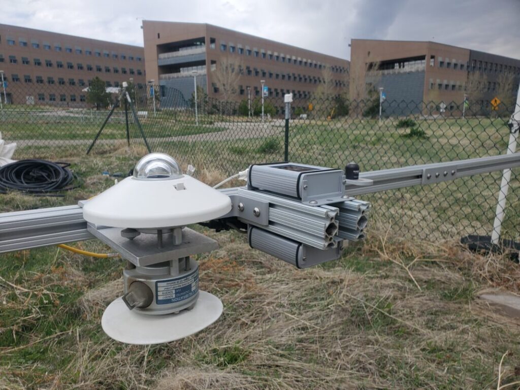
The IEC 61724-1 provide guidelines for albedo sensor placement, recommending a minimum height of 1m above the ground to capture an adequate field of view and allow for maintenance. The sensitivity of bifacial energy yield to albedo variations has been quantified, indicating that a 0.06 change in albedo causes a 1% change in simulated bifacial energy yield [19].
Performance modelling
Performance modelling of tracked PV systems involves estimating tracker angles, front and rear POA irradiance, module/cell temperature, reflection and spectral losses, shading, soiling, snow loss and applying an electrical model to determine the IV curve or maximum power point. Additional steps include calculating derate factors such as wiring and inverter losses. Rear side POA irradiance is the most difficult quantity to estimate.
There are two conventional methods used: view factors (VF) and ray tracing. The VF method uses analytic equations to calculate the fraction of irradiance leaving one surface and reaching another. While it is numerically fast, the method is not well suited to represent the detailed 3D design of tracker fields. Modelling software such as SAM, PVsyst and PVsol use VF methods. Ray tracing requires significant computing resources as it traces thousands of individual light rays from their source to the array including the effects of reflection off the ground and structures. An open-source example of a ray tracing software is bifacial_radiance developed by the National Renewable Energy Laboratory. A more advanced method, GPU-based 3D View Factors, relies on methods derived from computer games that utilise graphics processing units (GPUs) to rapidly calculate light distribution on 3D surfaces. Examples of these models include TNO (BigEye), University of Twente (VR4PV) and LuciSun (LuSim).
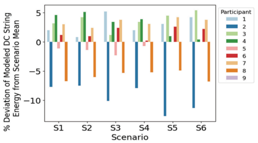
To evaluate the consistency of various PV performance models, a blind modelling intercomparison was conducted. Nine volunteer participants simulated a series of design scenarios. Unlike previous comparisons by the PV Performance Modelling Collaborative (PVPMC), this study did not use real systems with measured performance data. Instead, six predefined scenarios were used to assess model consistency. The scenarios defined different bifacial PV tracker systems and differed in the GCR, ground albedo, tracker height, module configuration and ground surface slope. Participants were provided with a year of hourly-averaged irradiance and weather data, module specifications and array specifications. They simulated each scenario and returned hourly results for front and rear POA irradiance, module temperatures, tracking angles and DC string power.
Despite all participants simulating the same scenarios, the results of their simulations varied significantly. The power results varied by +5% to -10% from the mean for each scenario, indicating a need for further model improvement and validation (Figure 5).
Detailed comparisons showed significant variability in front and rear POA irradiance, module temperatures and tracker rotation angles among participants. Rear POA irradiance differed as much as ~100% between participants. Overall, the study highlights the need for improved validation and standardisation of bifacial PV performance models to ensure consistent and accurate predictions are used for developing and financing these systems.
Reliability considerations
Compared to fixed-tilt PV systems, solar trackers add points of failure and moving components, necessitating more maintenance. The energy gain must outweigh the installation and maintenance costs, making reliability crucial. However, there is limited published research on solar tracking reliability, with much information derived from industry conversations.
Failures can be intrinsic (caused by the tracking system) or extrinsic (caused by external forces). Intrinsic failures may be mechanical or electrical, such as communication system failures, inaccurate tracking inputs, or mechanical component wear. Extrinsic failures are often due to environmental factors like wind blown sand or extreme weather. Wind, in particular, can cause catastrophic damage through torsional galloping.
Tracker failures typically result in the system getting stuck or moving incorrectly but rarely disconnect the PV array, allowing continued electricity generation. The economic impact is less severe than failures in power-generating components. Robust design and maintenance strategies are crucial to minimising the impact of tracker failures and ensuring reliable PV system performance.
In the owner/operator survey, mechanical failures, especially with slew drives and motors, were frequently cited as problems. Technical challenges like tracker misalignment and row-to-row shading persisted despite backtracking demonstrating that there is still a gap between theory and practice. Battery-powered trackers showed poor performance in northern winter climates, highlighting specific vulnerabilities.
Technical and financial optimisation for tracked bifacial PV systems
Optimising PV systems involves various technical approaches to enhance key performance indicators (KPIs) such as technology selection, O&M cost reduction, area utilisation, energy yield improvement and uncertainty reduction in yield estimates. However, a comprehensive optimisation requires a full financial model that reflects the overall project value from the investor’s perspective.
Key findings and areas for improvement
Tracking algorithms: Tracking companies avoid sharing details about how their tracking algorithms work, making it hard to evaluate their performance or value for bifacial technology. Developers interested in new tracking algorithms are encouraged to deploy multiple sets of trackers each running different algorithms at a site for a test period to help decide which one to use for the life of the plant. Side-by-side comparisons at the same site are necessary to validate industry claims of potential yield increases.
Albedo enhancement: It is not yet clear whether the use of albedo enhancers, such as geosynthetics, will ever be economically feasible, but early studies have shown some promising results. Continuing research into low-cost, durable materials and optimal placement strategies will help determine if albedo enhancement becomes standard practice.
Response to extreme weather: The ability of trackers to respond to extreme weather conditions should be standardised. According to our owner/operator survey, there is a significant risk that a tracker will not respond appropriately to such an event. While these events are rare, their consequences are very impactful.
Capacity tests: Despite improvements in monitoring bifacial tracked PV systems, challenges remain for capacity testing due to high DC/AC ratios, cloudy weather, and uncertainties in shading and yield predictions.
PV performance models: Yield prediction models for bifacial tracked systems need improvement. A comparison of models carried out on six scenarios showed up to 100% differences in rear-side irradiance predictions and variability in predictions for module temperatures and tracking angles. More validated datasets are needed for consistent modelling.
Reliability: There is very little literature on the reliability and durability of single-axis tracker systems. Longitudinal studies of different tracker technologies across different climates need to be supported. Such studies are important for optimising the design and operation of tracked PV plants.
References
[1] “International Technology Roadmap for Photovoltaic (ITRPV),” VDMA, 2024, vol. 15th Ed.
[2] C. D. Rodríguez-Gallegos et al., “Global Techno-Economic Performance of Bifacial and Tracking Photovoltaic Systems,” Joule, vol. 4, no. 7, pp. 1514-1541, 2020/07/15/ 2020, doi: https://doi.org/10.1016/j.joule.2020.05.005.
[3] K. Passow, J. Falls, and K. Hunt, “Sensitivity of PV Plant Performance to Tracker Error,” in 2019 IEEE 46th Photovoltaic Specialists Conference (PVSC), 16-21 June 2019 2019, pp. 0659- 0662, doi: 10.1109/PVSC40753.2019.8980662.
[4] E. Lorenzo et al, “Tracking and back-tracking,” Progress in Photovoltaics: Research and Applications, vol. 19, no. 6, pp. 747- 753, 2011, doi: https://doi.org/10.1002/pip.1085.
[5] K. Anderson, “Maximizing Yield with Improved SingleAxis Backtracking on Cross-Axis Slopes,” in 2020 47th IEEE Photovoltaic Specialists Conference (PVSC), 15 June-21 Aug. 2020, pp. 1466-1471, doi: 10.1109/PVSC45281.2020.9300438.
[6] K. S. Anderson et al, “Shaded fraction and backtracking in single-axis trackers on rolling terrain,” Journal of Renewable and Sustainable Energy, vol. 16, no. 2, 2024, doi: 10.1063/5.0202220.
[7] K. Rhee, “Terrain Aware Backtracking via Forward Ray Tracing,” in 2022 IEEE 49th Photovoltaics Specialists Conference (PVSC), 5-10 June 2022 2022, pp. 0029-0030, doi: 10.1109/PVSC48317.2022.9938554.
[8] A. Dobos, “Improved Tracking Schemes for Half-Cut PV Modules,” presented at the 2022 PV Performance Modeling Collaborative (PVPMC) Workshop, Salt Lake City, 2022.
[9] N. A. Kelly and T. L. Gibson, “Increasing the solar photovoltaic energy capture on sunny and cloudy days,” Solar Energy, vol. 85, no. 1, pp. 111-125, 2011/01/01/ 2011, doi: https://doi.org/10.1016/j.solener.2010.10.015.
[10] J. E. Ramírez, “Harnessing Smart Solar Tracking: Advanced Algorithms for Hail Protection,” in “Soltec Whitepaper,” 2023. [Online]. Available: https://soltec.com/uploads/2023/11/ Whitepaper-Hail-1.pdf
[11] M. R. Lewis, S. Ovaitt et al, “Artificial ground reflector size and position effects on energy yield and economics of single-axistracked bifacial photovoltaics,” Progress in Photovoltaics: Research and Applications, vol. n/a, no. n/a, 2024, doi: https://doi.org/10.1002/pip.3811.
[12] M. Sengupta et al, “Best Practices Handbook for the Collection and Use of Solar Resource Data for Solar Energy Applications,” 2024, vol. Fourth Edition.
[13] M. Korevaar et al, “Simulation of POA Front Sensor Mounting,” in 2023 European PVPMC, Mendrisio, Switzerland, 2023, https:// pvpmc.sandia.gov/workshops-and-pubs/workshops/2023- pvpmc-mendrisio/
[14] S. A. Pelaez, C. Deline, J. S. Stein et al, “Effect of torque-tube parameters on rear-irradiance and rear-shading loss for bifacial PV performance on single-axis tracking systems,” in 2019 IEEE 46th Photovoltaic Specialists Conference (PVSC), 16-21 June 2019 2019, vol. 2, pp. 1-6, doi: 10.1109/PVSC40753.2019.9198975.
[15] N. Riedel-Lyngskær, M. Petit, D. Berrian, P. B. Poulsen, J. Libal, and M. L. Jakobsen, “A Spatial Irradiance Map Measured on the Rear Side of a Utility-Scale Horizontal Single Axis Tracker with Validation using Open Source Tools,” in 2020 47th IEEE Photovoltaic Specialists Conference (PVSC), 15 June-21 Aug. 2020 2020, pp. 1026-1032, doi: 10.1109/PVSC45281.2020.9300608.
[16] N. Riedel-Lyngskær et al, “Measuring Irradiance With Bifacial Reference Panels,” IEEE Journal of Photovoltaics, vol. 12, no. 6, pp. 1324-1333, 2022, doi: 10.1109/JPHOTOV.2022.3201468.
[17] J. Polo, M. Alonso-Abella et al, “On the use of reference modules in characterizing the performance of bifacial modules for rooftop canopy applications,” Renewable Energy, vol. 220, p. 119672, 2024/01/01/ 2024, doi: https://doi.org/10.1016/j.renene.2023.119672.
[18] K. Anderson et al, “A Method for Estimating Time-Series PV Production Loss From Solar Tracking Failures,” IEEE Journal of Photovoltaics, vol. 12, no. 1, pp. 119-126, 2022, doi: 10.1109/JPHOTOV.2021.3123872.
[19] H. Darling and e. al., “Impacts of Albedo Estimation Method on Energy Estimates,” in 2023 PVPMC Workshop, Salt Lake City, UT, 2023.
About the authors
Joshua S. Stein, senior scientist at Sandia National Laboratoris, leads R&D projects in the areas of PV module and system performance and reliability. He leads the Photovoltaic Accelerator for Commercializing Technologies (PACT), is the founder of the PV Performance Modeling Collaborative (PVPMC) and represents the United States in the International Energy Agency PVPS Task 13 on PV Performance and Reliability.
Giosuè Maugeri is a researcher at Ricerca sul Sistema Energetico – RSE S.p.A., where he has been working since 2011. He leads the PV Test Lab, coordinating research activities focused on PV reliability and performance efficiency, with particular emphasis on developing tools for remote fault detection and diagnosis in utility-scale PV systems.
Silvana Ovaitt is a researcher at National Renewable Energy Laboratory (NREL), focusing on bifacial PV technology performance and reliability. Her work extends into the circular economy, developing tools to assess PV sustainability. Silvana leads the Hands-on PV Experience (HOPE) Workshop, offering PhD students industry-relevant experience.
Thore Müller is CEO of PVRADAR Labs, with expertise in soiling mitigation and albedo enhancement. He began his career in applied research and testing of innovative technologies at the El Aguila Research and Innovation Center in Chile. Today, he develops models and software that enable project developers to refine and improve their designs.


